Press Enter to jump to the next word.
Revision history #
| Version | Date | Editor | Description of changes |
| 1.0 | 04.2025 |
OD |
Basic version |
Introduction #
This document presents the Task catalogue of the UNUM Genset telematics service for diesel generators (hereinafter referred to as the task catalogue), developed by Technoton.
Task catalogue is intended for professionals responsible for the deployment, configuration, maintenance, and day-to-day operation of the UNUM Genset telematics service.
The catalogue serves as a reference guide for selecting functions, configuring, and adapting the UNUM Genset service to the specific operating conditions of its monitored assets—diesel generator sets (gensets).
 |
RECOMMENDATION: Before using the Task Catalogue, it is strongly recommended to review the information provided in the following documents: “UNUM Genset Telematics service. “Fleet”. User manual”. “UNUM IIoT Platform. “Industry solution”. User manual”. |
Tasks are billable services within the UNUM Genset system and include:
- real-time monitoring of genset operation via dashboards;
- analysis of genset performance data over a selected period using analytical reports.
The services are provided to a specific asset or group on a subscription basis and include access to dashboard and report templates with preconfigured key sets, according to the task class.
Tasks are created and modified exclusively by the solution owner — Technoton. If needed, any number of custom tasks can be created.
In addition to the preconfigured “Fleet”-level templates, additional dashboards/reports can be created as needed for the tasks.
Keys are data units included in tasks. Each key has a defined set of attributes: SA (Source Address) – the network address of the data source; SPN / VSPN – the monitored parameter of the asset’s/group operation; SPEC – a specification qualifier for the parameter
(if applicable).
Each key corresponds to a single monitored parameter obtained from a specific source (sensor, ECU, etc.) and processed within the scope of a task. By default, predefined tasks are populated with keys up to a maximum of 90%. At the “Fleet” level, available free keys* in a task can be supplemented with additional SPNs/VSPNs.
Classes are categories of tasks defined by the volume of data included in processing. Each class is determined by the total number of predefined keys it contains, which corresponds to the class name: 25, 50, 100, 200**, 400**, 800**.
* To monitor parameters added by the user to available free keys, the installation of
corresponding additional hardware may be required.
** Implementation in progress.
Key Features of UNUM Genset tasks:
- Tariff-based system – Tasks are provided as paid telematics services with daily billing.
- Individual asset subscription – Each task is activated specifically for a selected asset.
- Parameter-based classification – Tasks are categorized by the number of parameters, enabling optimal selection based on genset model and operating conditions.
- Preconfigured parameters – Every task includes a predefined set of SPN/VSPN keys tailored to its functional purpose.
- Universality – Compatible with gensets of various brands and engine models; supports most major genset controller brands worldwide.
- Flexible configuration – Tasks can be freely combined, allowing adaptation to various asset setups and required numbers of monitored parameters.
|
WARNING: Technoton reserves the right to make changes to the tasks presented in this catalogue without prior notice to users, provided that the quality and functionality of the UNUM Genset service are maintained. |
1 Tasks for monitoring single gensets #
1.1 Fuel Monitoring Basic #
Task class: 25.
Purpose:
Fuel Monitoring Basic is designed for real-time monitoring or analysis over a selected period of key fuel-related parameters, including fuel le vel in the tank, fuel consumption in the supply line, and engine operating time of the genset.
Equipment used:
- DUT-E / DUT-E 2Bio / DUT-E S7 / DUT-E 2Bio S7 fuel level sensor – 1 pc.;
- DFM / DFM D / DFM S7 / DFM D S7 fuel flow meter – 1 pc.;
- CANUp 27 Genset telematics gateway – 1 pc.
Total keys: 25 pcs.
Preconfigured keys: 22 pcs. (see table 1).
Free keys: 3 pcs.
Table 1 — Preconfigured keys for the Fuel Monitoring Basic task
| Source network address | SPN and specifier (if applicable) |
Unit of measurement | Description |
| 101 | 96 Fuel Level 1 | % | Current value (in %) of the fuel level in the tank in relation to the level of the full tank. |
| 101 | 174 Engine Fuel Temp | °C | Current value of fuel temperature in the tank. |
| 111 | 174 Engine Fuel Temp | °C | Current value of fuel temperature in the flow meter measuring chamber. |
| 111 | 183 Engine fuel rate | l/h | Hourly rate consumption of fuel, going through measuring chamber of flow meter (applicable for one-chamber). For differential flow meter – hourly rate of differential consumption of fuel, going through both measuring chambers. |
| 101 | 250 Total fuel used | l | Engine fuel consumption based on data from the fuel level sensor in the tank. |
| 111 | 1834 Engn Tot.Aver. Fuel Rate | l/h | Average hourly fuel consumption by the engine. |
| 134 | 2445 A-N AC RMS Voltage | V | Generator voltage L1 (A) – N (Neutral) based on data from the control panel. |
| 111 | 5054 High Res.Total Fuel Used | l | Counter of total fuel consumption by the engine within the whole range of loads. The counter is increasing from the date of flow meter production and cannot be reset by user. |
| 111 | 5054 High Res.Total Fuel Used 28. Counter Type : 0. Clearable |
l | Resettable counter of total time of the flow meter operation within the whole range of loads, including the “Idle” mode of engine operation. The counter indications increment from the moment of its previous reset by the user. |
| 111 | 5054 High Res.Total Fuel Used 9. Movement mode based on fuel rate : 0. Idle |
l | Counter of total fuel consumption by the engine in the “Idle” mode operation. The counter is increasing from the date of flow meter production and cannot be reset by user. |
| 111 | 5054 High Res.Total Fuel Used 9. Movement mode based on fuel rate : 1. Optimal |
l | Counter of total fuel consumption by the engine in the “Optimal” mode operation. The counter is increasing from the date of flow meter production and cannot be reset by user. |
| 111 | 5054 High Res.Total Fuel Used 9. Movement mode based on fuel rate : 2. Overload |
l | Counter of total fuel consumption by the engine in the “Overload” mode operation. The counter is increasing from the date of flow meter production and cannot be reset by user. |
| 111 | 5054 High Res.Total Fuel Used 9. Movement mode based on fuel rate : 3. Cheating |
l | Counter of total fuel consumption by the engine which exceeded the upper limit set for this particular flow meter model. Increasing numbers on the counter can mean either possible fuel line intervention or incorrect installation of fuel flow meter. The counter is increasing from the date of flow meter production and cannot be reset by user. |
| 101 | 521024 Fuel Tank Volume 2. Mathematical processing : 10. Filtering |
l | The value of the fuel volume in tank filtered according to the preset time interval. |
| 111 | 521028 Chamber Working Mode 18. Chamber type : 0. Feed chamber | No | Current operation mode of fuel consumer, correspondent to hourly rate of fuel consumption in “Feed” chamber of differential fuel flow meter. |
| 100 | 521055 Vehicle Power Supp.Volt. | V | Current onboard voltage value based on data from the telematics gateway. |
| 111 | 521171 Flowmet.Hours Of Operat. | s | Counter of total time of the flow meter operation within the whole range of loads. The counter is increasing from the date of flow meter production and cannot be reset by user. |
| 111 | 521171 Flowmet.Hours Of Operat. 9. Movement mode based on fuel rate : 5. Interference | s | Counter of total time of external factors impact (e.g. strong magnetic field) impeding the flow meter operation. The counter is increasing from the date of flow meter production and cannot be reset by user. |
| 111 | 521267 Interference sens.count | pcs. | Number of detected tampering events involving the flow meter. |
| 101 | 521301 Filled Fuel Volume | l | Volume of fuel filled during a recorded “Fuelling” event. |
| 101 | 521302 Discharged Fuel Volume | l | Volume of fuel drained during a recorded “Fuel discharging” event. |
| 111 | 521310 Interference Duration | s | Duration of intervention in the flow meter operation when the “Interference” event is recorded. |
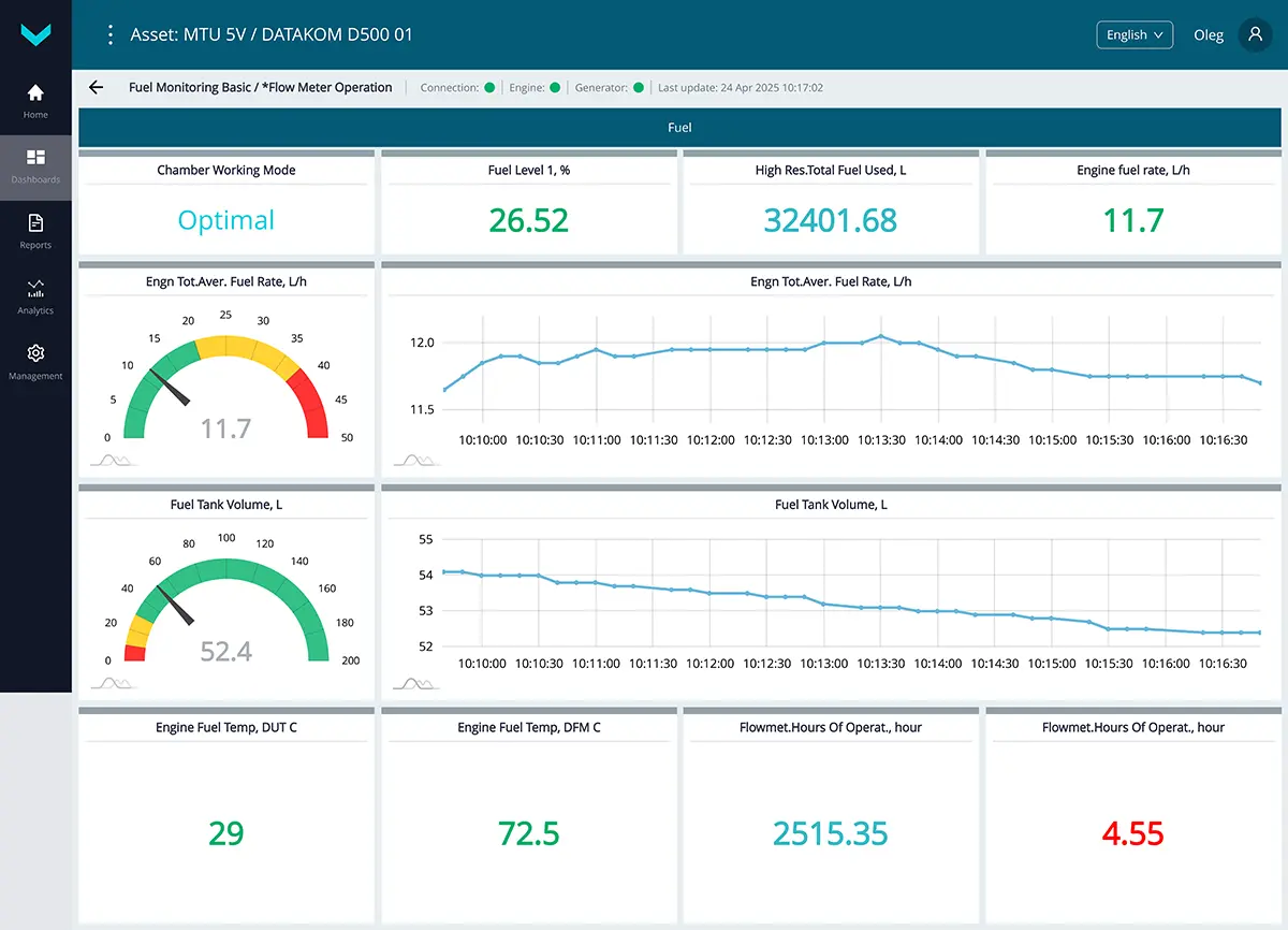
a) real-time display of information on the *Flow Meter Operation dashboard
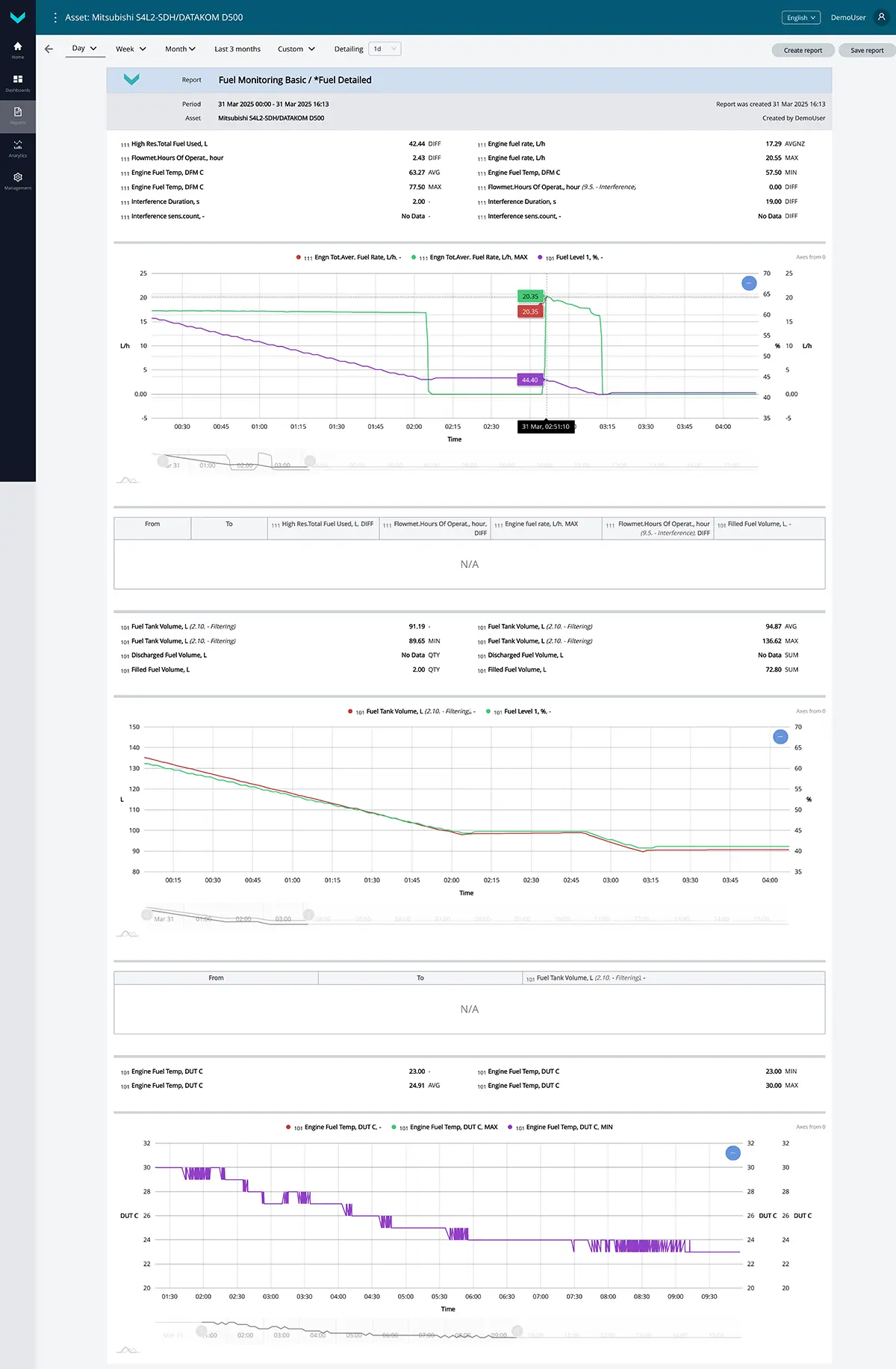
b) analytical report *Fuel Detailed for the “one-day” period
Figure 1 — Examples of default data display for the Fuel Monitoring Basic task
1.2 Fuel Monitoring Standard #
Task class: 50.
Purpose:
Fuel Monitoring Standard — this task is designed for real-time monitoring or analysis over a selected period of detailed data, including fuel level and volume in the tank, fuel temperature, as well as fuel consumption and engine runtime of the genset (total and by load modes, including supply and return lines in case of differential measurement).
Equipment used:
- DUT-E / DUT-E 2Bio / DUT-E S7 / DUT-E 2Bio S7 fuel level sensor – 1 pc.;
- DFM / DFM D / DFM S7 / DFM D S7 fuel flow meter – 1 pc.;
- CANUp 27 Genset telematics gateway – 1 pc.
Total keys: 50 pcs.
Preconfigured keys: 36 pcs. (see table 2).
Free keys: 14 pcs.
Table 2 — Preconfigured keys for the Fuel Monitoring Standard task
| Source network address | SPN and specifier (if applicable) |
Unit of measurement | Description |
| 101 | 96 Fuel Level 1 | % | Current value (in %) of the fuel level in the tank in relation to the level of the full tank. |
| 111 | 158 On-board voltage | V | Onboard voltage (from the ignition switch) based on data from the flow meter. |
| 101 | 158 On-board voltage | V | Onboard voltage (from the ignition switch) based on data from the fuel level sensor. |
| 101 | 174 Engine Fuel Temp | °C | Current value of fuel temperature in the tank. |
| 111 | 174 Engine Fuel Temp | °C | Current value of fuel temperature in the flow meter measuring chamber. |
| 111 | 183 Engine fuel rate | l/h | Hourly rate consumption of fuel, going through measuring chamber of flow meter (applicable for one-chamber). For differential flow meter – hourly rate of differential consumption of fuel, going through both measuring chambers. |
| 101 | 250 Total fuel used | l | Engine fuel consumption based on data from the fuel level sensor in the tank. |
| 111 | 1834 Engn Tot.Aver. Fuel Rate | l/h | Average hourly fuel consumption by the engine. |
| 111 | 5054 High Res.Total Fuel Used | l | Counter of total fuel consumption by the engine within the whole range of loads. The counter is increasing from the date of flow meter production and cannot be reset by user. |
| 111 | 5054 High Res.Total Fuel Used 18. Chamber type : 0. Feed chamber |
l | Counter of total fuel consumption by the engine in the “Feed” chamber of the differential flow meter within the whole range of loads. The counter is increasing from the date of flow meter production and cannot be reset by user. |
| 111 | 5054 High Res.Total Fuel Used 18. Chamber type : 1. Reverse chamber |
l | Counter of total fuel consumption by the engine in the “Reverse” chamber of the differential flow meter within the whole range of loads. The counter is increasing from the date of flow meter production and cannot be reset by user. |
| 111 | 5054 High Res.Total Fuel Used 9. Movement mode based on fuel rate : 0. Idle |
l | Counter of total fuel consumption by the engine in the “Idle” mode operation. The counter is increasing from the date of flow meter production and cannot be reset by user. |
| 111 | 5054 High Res.Total Fuel Used 9. Movement mode based on fuel rate : 1. Optimal |
l | Counter of total fuel consumption by the engine in the “Optimal” mode operation. The counter is increasing from the date of flow meter production and cannot be reset by user. |
| 111 | 5054 High Res.Total Fuel Used 9. Movement mode based on fuel rate : 2. Overload |
l | Counter of total fuel consumption by the engine in the “Overload” mode operation. The counter is increasing from the date of flow meter production and cannot be reset by user. |
| 111 | 5054 High Res.Total Fuel Used 9. Movement mode based on fuel rate : 3. Cheating |
l | Counter of total fuel consumption by the engine which exceeded the upper limit set for this particular flow meter model.
Increasing numbers on the counter can mean either possible fuel line intervention or incorrect installation of fuel flow meter. The counter is increasing from the date of flow meter production and cannot be reset by user. |
| 111 | 5054 High Res.Total Fuel Used 28. Counter Type : 0. Clearable |
l | Resettable counter of total time of the flow meter operation within the whole range of loads, including the “Idle” mode of engine operation. The counter indications increment from the moment of its previous reset by the user. |
| 101 | 521023 Fuel Tank Level | mm | Fuel level value in the tank. |
| 101 | 521024 Fuel Tank Volume 2. Mathematical processing : 10. Filtering |
l | The value of the fuel volume in tank filtered according to the preset time interval. |
| 100 | 521055 Vehicle Power Supp.Volt. | V | Current onboard voltage value based on data from the telematics gateway. |
| 111 | 521129 Unit Power Status | No | Current power-supply status of the flow meter: – powered from embedded power source; – powered from on-board electrical system; – power is off; – power-supply status is not available/not supported by this device. |
| 111 | 521171 Flowmet.Hours Of Operat. | s | Counter of total time of the flow meter operation within the whole range of loads. The counter is increasing from the date of flow meter production and cannot be reset by user. |
| 111 | 521171 Flowmet.Hours Of Operat. 9. Movement mode based on fuel rate : 0. Idle | s | Counter of total time of the flow meter operation within the “Idle” mode of engine operation. The counter is increasing from the date of flow meter production and cannot be reset by user. |
| 111 | 521171 Flowmet.Hours Of Operat. 9. Movement mode based on fuel rate : 1. Optimal | s | Counter of total time of the flow meter operation within the “Optimal” mode of engine operation. The counter is increasing from the date of flow meter production and cannot be reset by user. |
| 111 | 521171 Flowmet.Hours Of Operat. 9. Movement mode based on fuel rate : 2. Overload | s | Counter of total time of the flow meter operation within the “Overload” mode of engine operation. The counter is increasing from the date of flow meter production and cannot be reset by user. |
| 111 | 521171 Flowmet.Hours Of Operat. 9. Movement mode based on fuel rate : 3. Cheating | s | Counter of total time of the flow meter operation during which the upper limit of fuel consumption set for the mounted flow meter model was exceeded. The counter is increasing from the date of flow meter production and cannot be reset by user. |
| 111 | 521171 Flowmet.Hours Of Operat. 9. Movement mode based on fuel rate : 5. Interference | s | Counter of total time of external factors impact (e.g. strong magnetic field) impeding the flow meter operation. The counter is increasing from the date of flow meter production and cannot be reset by user. |
| 111 | 521171 Flowmet.Hours Of Operat. 28. Counter Type : 0. Clearable |
s | Resettable counter of total time of the flow meter operation within the whole range of loads. The counter indications increment from the moment of its previous reset by the user. |
| 111 | 521181 Engn Mode by Fuel Rate | No | Current operation mode of fuel consumer, correspondent to hourly rate of fuel consumption (applicable for one-chamber flow meter). For differential flow meter – current operation mode of fuel consumer, correspondent to hourly differential rate of fuel consumption. |
| 111 | 521267 Interference sens.count | pcs. | Number of detected tampering events involving the flow meter. |
| 101 | 521301 Filled Fuel Volume | l | Volume of fuel filled during a recorded “Fuelling” event. |
| 101 | 521302 Discharged Fuel Volume | l | Volume of fuel drained during a recorded “Fuel discharging” event. |
| 111 | 521309 Cheating Fuel Volume | l | Volume of simulated fuel flow during a recorded “Flow meter tampering” event. |
| 111 | 521310 Interference Duration | s | Duration of intervention in the flow meter operation when the “Interference” event is recorded. |
| 111 | 521313 Engine fuel rate | m³/h | Hourly fuel consumption. |
| 111 | 521314 Total Fuel Used | h³ | Total fuel consumption. |
| 101 | 521440 Frequency (Duty Cycle) | Hz | Fuel level sensor measuring generator frequency. |
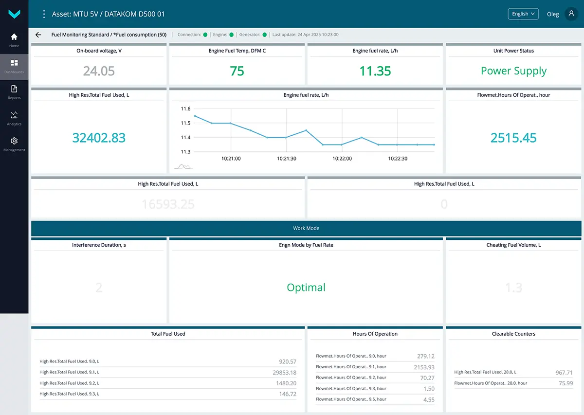
a) real-time display of information on the *Fuel consumption (50) dashboard
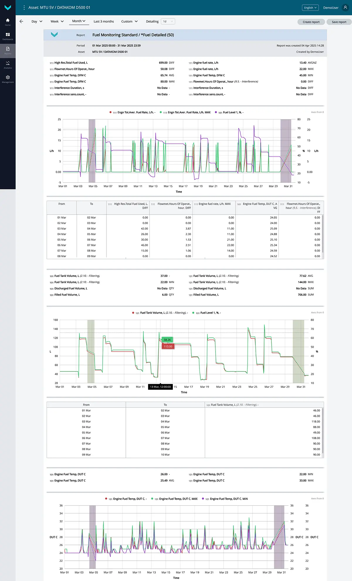
b) analytical report *Fuel Detailed (50) for the “one-month” period
Figure 2 — Examples of default data display for the Fuel Monitoring Standard task
1.3 Fuel Monitoring Genset Pool #
Task class: 100.
Purpose:
Fuel Monitoring Genset Pool — this task is intended for real-time monitoring or analysis over a selected period of key information on fuel level and volume in tanks, fuel consumption in fuel lines, and engine runtime for a pool of four gensets.
Equipment used:
- DUT-E / DUT-E 2Bio / DUT-E S7 / DUT-E 2Bio S7 fuel level sensor – 4 pcs.;
- DFM / DFM D / DFM S7 / DFM D S7 fuel flow meter – 4 pcs.;
- CANUp 27 Genset telematics gateway – 1 pc.
Total keys: 100 pcs.
Preconfigured keys: 80 pcs. (see table 3).
Free keys: 20 pcs.
Table 3 — Preconfigured keys for the Fuel Monitoring Genset Pool task
| Source network address | SPN and specifier (if applicable) |
Unit of measurement | Description |
| 101 | 96 Fuel Level 1 | % | Current value (in %) of the fuel level in the tank in relation to the level of the full tank (for genset 1). |
| 102 | 96 Fuel Level 1 | % | Current value (in %) of the fuel level in the tank in relation to the level of the full tank (for genset 2). |
| 103 | 96 Fuel Level 1 | % | Current value (in %) of the fuel level in the tank in relation to the level of the full tank (for genset 3). |
| 104 | 96 Fuel Level 1 | % | Current value (in %) of the fuel level in the tank in relation to the level of the full tank (for genset 4). |
| 101 | 158 On-board voltage | V | Onboard voltage (from the ignition switch) based on data from the fuel level sensor (for genset 1). |
| 102 | 158 On-board voltage | V | Onboard voltage (from the ignition switch) based on data from the fuel level sensor (for genset 2). |
| 103 | 158 On-board voltage | V | Onboard voltage (from the ignition switch) based on data from the fuel level sensor (for genset 3). |
| 104 | 158 On-board voltage | V | Onboard voltage (from the ignition switch) based on data from the fuel level sensor (for genset 4). |
| 111 | 158 On-board voltage | V | Onboard voltage (from the ignition switch) based on data from the flow meter (for genset 1). |
| 112 | 158 On-board voltage | V | Onboard voltage (from the ignition switch) based on data from the flow meter (for genset 2). |
| 113 | 158 On-board voltage | V | Onboard voltage (from the ignition switch) based on data from the flow meter (for genset 3). |
| 114 | 158 On-board voltage | V | Onboard voltage (from the ignition switch) based on data from the flow meter (for genset 4). |
| 101 | 174 Engine Fuel Temp | °C | Current value of fuel temperature in the tank (for genset 1). |
| 102 | 174 Engine Fuel Temp | °C | Current value of fuel temperature in the tank (for genset 2). |
| 103 | 174 Engine Fuel Temp | °C | Current value of fuel temperature in the tank (for genset 3). |
| 104 | 174 Engine Fuel Temp | °C | Current value of fuel temperature in the tank (for genset 4). |
| 111 | 174 Engine Fuel Temp | °C | Current value of fuel temperature in the flow meter measuring chamber (for genset 1). |
| 112 | 174 Engine Fuel Temp | °C | Current value of fuel temperature in the flow meter measuring chamber (for genset 2). |
| 113 | 174 Engine Fuel Temp | °C | Current value of fuel temperature in the flow meter measuring chamber (for genset 3). |
| 114 | 174 Engine Fuel Temp | °C | Current value of fuel temperature in the flow meter measuring chamber (for genset 4). |
| 111 | 183 Engine fuel rate | l/h | Hourly rate consumption of fuel, going through measuring chamber of flow meter (applicable for one-chamber). For differential flow meter – hourly rate of differential consumption of fuel, going through both measuring chambers (for genset 1). |
| 112 | 183 Engine fuel rate | l/h | Hourly rate consumption of fuel, going through measuring chamber of flow meter (applicable for one-chamber). For differential flow meter – hourly rate of differential consumption of fuel, going through both measuring chambers (for genset 2). |
| 113 | 183 Engine fuel rate | l/h | Hourly rate consumption of fuel, going through measuring chamber of flow meter (applicable for one-chamber). For differential flow meter – hourly rate of differential consumption of fuel, going through both measuring chambers (for genset 3). |
| 114 | 183 Engine fuel rate | l/h | Hourly rate consumption of fuel, going through measuring chamber of flow meter (applicable for one-chamber). For differential flow meter – hourly rate of differential consumption of fuel, going through both measuring chambers (for genset 4). |
| 111 | 5054 High Res.Total Fuel Used | l | Counter of total fuel consumption by the engine within the whole range of loads. The counter is increasing from the date of flow meter production and cannot be reset by user (for genset 1). |
| 111 | 5054 High Res.Total Fuel Used 18. Chamber type : 0. Feed chamber |
l | Counter of total fuel consumption by the engine in the “Feed” chamber of the differential flow meter within the whole range of loads. The counter is increasing from the date of flow meter production and cannot be reset by user (for genset 1). |
| 111 | 5054 High Res.Total Fuel Used 18. Chamber type : 1. Reverse chamber |
l | Counter of total fuel consumption by the engine in the “Reverse” chamber of the differential flow meter within the whole range of loads. The counter is increasing from the date of flow meter production and cannot be reset by user (for genset 1). |
| 112 | 5054 High Res.Total Fuel Used | l | Counter of total fuel consumption by the engine within the whole range of loads. The counter is increasing from the date of flow meter production and cannot be reset by user (for genset 2). |
| 112 | 5054 High Res.Total Fuel Used 18. Chamber type : 0. Feed chamber |
l | Counter of total fuel consumption by the engine in the “Feed” chamber of the differential flow meter within the whole range of loads. The counter is increasing from the date of flow meter production and cannot be reset by user (for genset 2). |
| 112 | 5054 High Res.Total Fuel Used 18. Chamber type : 1. Reverse chamber |
l | Counter of total fuel consumption by the engine in the “Reverse” chamber of the differential flow meter within the whole range of loads. The counter is increasing from the date of flow meter production and cannot be reset by user (for genset 2). |
| 113 | 5054 High Res.Total Fuel Used | l | Counter of total fuel consumption by the engine within the whole range of loads. The counter is increasing from the date of flow meter production and cannot be reset by user (for genset 3). |
| 113 | 5054 High Res.Total Fuel Used 18. Chamber type : 0. Feed chamber |
l | Counter of total fuel consumption by the engine in the “Feed” chamber of the differential flow meter within the whole range of loads. The counter is increasing from the date of flow meter production and cannot be reset by user (for genset 3). |
| 113 | 5054 High Res.Total Fuel Used 18. Chamber type : 1. Reverse chamber |
l | Counter of total fuel consumption by the engine in the “Reverse” chamber of the differential flow meter within the whole range of loads. The counter is increasing from the date of flow meter production and cannot be reset by user (for genset 3). |
| 114 | 5054 High Res.Total Fuel Used | l | Counter of total fuel consumption by the engine within the whole range of loads.
The counter is increasing from the date of flow meter production and cannot be reset by user |
| 114 | 5054 High Res.Total Fuel Used 18. Chamber type : 0. Feed chamber |
l | Counter of total fuel consumption by the engine in the “Feed” chamber of the differential flow meter within the whole range of loads. The counter is increasing from the date of flow meter production and cannot be reset by user (for genset 4). |
| 114 | 5054 High Res.Total Fuel Used 18. Chamber type : 1. Reverse chamber |
l | Counter of total fuel consumption by the engine in the “Reverse” chamber of the differential flow meter within the whole range of loads. The counter is increasing from the date of flow meter production and cannot be reset by user (for genset 4). |
| 101 | 521023 Fuel Tank Level 2. Mathematical processing : 10. Filtering |
mm | Fuel level value in the tank, filtered by the specified time interval (for genset 1). |
| 102 | 521023 Fuel Tank Level 2. Mathematical processing : 10. Filtering |
mm | Fuel level value in the tank, filtered by the specified time interval (for genset 2). |
| 103 | 521023 Fuel Tank Level 2. Mathematical processing : 10. Filtering |
mm | Fuel level value in the tank, filtered by the specified time interval (for genset 3). |
| 104 | 521023 Fuel Tank Level 2. Mathematical processing : 10. Filtering |
mm | Fuel level value in the tank, filtered by the specified time interval (for genset 4). |
| 101 | 521024 Fuel Tank Volume 2. Mathematical processing : 10. Filtering |
l | The value of the fuel volume in tank filtered according to the preset time interval (for genset 1). |
| 102 | 521024 Fuel Tank Volume 2. Mathematical processing : 10. Filtering |
l | The value of the fuel volume in tank filtered according to the preset time interval (for genset 2). |
| 103 | 521024 Fuel Tank Volume 2. Mathematical processing : 10. Filtering |
l | The value of the fuel volume in tank filtered according to the preset time interval (for genset 3). |
| 104 | 521024 Fuel Tank Volume 2. Mathematical processing : 10. Filtering |
l | The value of the fuel volume in tank filtered according to the preset time interval (for genset 4). |
| 111 | 521171 Flowmet.Hours Of Operat. | s | Counter of total time of the flow meter operation within the whole range of loads. The counter is increasing from the date of flow meter production and cannot be reset by user (for genset 1). |
| 111 | 521171 Flowmet.Hours Of Operat. 9. Movement mode based on fuel rate : 0. Idle |
s | Counter of total time of the flow meter operation within the “Idle” mode of engine operation. The counter is increasing from the date of flow meter production and cannot be reset by user (for genset 1). |
| 111 | 521171 Flowmet.Hours Of Operat. 9. Movement mode based on fuel rate : 1. Optimal |
s | Counter of total time of the flow meter operation within the “Optimal” mode of engine operation. The counter is increasing from the date of flow meter production and cannot be reset by user (for genset 1). |
| 111 | 521171 Flowmet.Hours Of Operat. 9. Movement mode based on fuel rate : 2. Overload |
s | Counter of total time of the flow meter operation within the “Overload” mode of engine operation. The counter is increasing from the date of flow meter production and cannot be reset by user (for genset 1). |
| 111 | 521171 Flowmet.Hours Of Operat. 9. Movement mode based on fuel rate : 3. Cheating |
s | Counter of total time of the flow meter operation during which the upper limit of fuel consumption set for the mounted flow meter model was exceeded. The counter is increasing from the date of flow meter production and cannot be reset by user (for genset 1). |
| 111 | 521171 Flowmet.Hours Of Operat. 9. Movement mode based on fuel rate : 4. Negative |
s | Counter of total time of the flow meter operation during which the amount of fuel coming back through the reverse line exceeded fuel consumption in the feed line. This counter is foreseen only for differential models of flow meters. The counter can be found only in differential fuel flow meters. The counter is increasing from the date of flow meter production and cannot be reset by user (for genset 1). |
| 112 | 521171 Flowmet.Hours Of Operat. | s | Counter of total time of the flow meter operation within the whole range of loads. The counter is increasing from the date of flow meter production and cannot be reset by user (for genset 2). |
| 112 | 521171 Flowmet.Hours Of Operat. 9. Movement mode based on fuel rate : 0. Idle |
s | Counter of total time of the flow meter operation within the “Idle” mode of engine operation. The counter is increasing from the date of flow meter production and cannot be reset by user (for genset 2). |
| 112 | 521171 Flowmet.Hours Of Operat. 9. Movement mode based on fuel rate : 1. Optimal |
s | Counter of total time of the flow meter operation within the “Optimal” mode of engine operation. The counter is increasing from the date of flow meter production and cannot be reset by user (for genset 2). |
| 112 | 521171 Flowmet.Hours Of Operat. 9. Movement mode based on fuel rate : 2. Overload |
s | Counter of total time of the flow meter operation within the “Overload” mode of engine operation. The counter is increasing from the date of flow meter production and cannot be reset by user (for genset 2). |
| 112 | 521171 Flowmet.Hours Of Operat. 9. Movement mode based on fuel rate : 3. Cheating |
s | Counter of total time of the flow meter operation during which the upper limit of fuel consumption set for the mounted flow meter model was exceeded. The counter is increasing from the date of flow meter production and cannot be reset by user (for genset 2). |
| 112 | 521171 Flowmet.Hours Of Operat. 9. Movement mode based on fuel rate : 4. Negative |
s | Counter of total time of the flow meter operation during which the amount of fuel coming back through the reverse line exceeded fuel consumption in the feed line. This counter is foreseen only for differential models of flow meters. The counter can be found only in differential fuel flow meters. The counter is increasing from the date of flow meter production and cannot be reset by user (for genset 2). |
| 113 | 521171 Flowmet.Hours Of Operat. | s | Counter of total time of the flow meter operation within the whole range of loads. The counter is increasing from the date of flow meter production and cannot be reset by user (for genset 3). |
| 113 | 521171 Flowmet.Hours Of Operat. 9. Movement mode based on fuel rate : 0. Idle |
s | Counter of total time of the flow meter operation within the “Idle” mode of engine operation. The counter is increasing from the date of flow meter production and cannot be reset by user (for genset 3). |
| 113 | 521171 Flowmet.Hours Of Operat. 9. Movement mode based on fuel rate : 1. Optimal |
s | Counter of total time of the flow meter operation within the “Optimal” mode of engine operation. The counter is increasing from the date of flow meter production and cannot be reset by user (for genset 3). |
| 113 | 521171 Flowmet.Hours Of Operat. 9. Movement mode based on fuel rate : 2. Overload |
s | Counter of total time of the flow meter operation within the “Overload” mode of engine operation. The counter is increasing from the date of flow meter production and cannot be reset by user (for genset 3). |
| 113 | 521171 Flowmet.Hours Of Operat. 9. Movement mode based on fuel rate : 3. Cheating |
s | Counter of total time of the flow meter operation during which the upper limit of fuel consumption set for the mounted flow meter model was exceeded. The counter is increasing from the date of flow meter production and cannot be reset by user (for genset 3). |
| 113 | 521171 Flowmet.Hours Of Operat. 9. Movement mode based on fuel rate : 4. Negative | s | Counter of total time of the flow meter operation during which the amount of fuel coming back through the reverse line exceeded fuel consumption in the feed line. This counter is foreseen only for differential models of flow meters. The counter can be found only in differential fuel flow meters. The counter is increasing from the date of flow meter production and cannot be reset by user (for genset 3). |
| 114 | 521171 Flowmet.Hours Of Operat. | s | Counter of total time of the flow meter operation within the whole range of loads. The counter is increasing from the date of flow meter production and cannot be reset by user (for genset 4). |
| 114 | 521171 Flowmet.Hours Of Operat. 9. Movement mode based on fuel rate : 0. Idle |
s | Counter of total time of the flow meter operation within the “Idle” mode of engine operation. The counter is increasing from the date of flow meter production and cannot be reset by user (for genset 4). |
| 114 | 521171 Flowmet.Hours Of Operat. 9. Movement mode based on fuel rate : 1. Optimal |
s | Counter of total time of the flow meter operation within the “Optimal” mode of engine operation. The counter is increasing from the date of flow meter production and cannot be reset by user (for genset 4). |
| 114 | 521171 Flowmet.Hours Of Operat. 9. Movement mode based on fuel rate : 2. Overload |
s | Counter of total time of the flow meter operation within the “Overload” mode of engine operation. The counter is increasing from the date of flow meter production and cannot be reset by user (for genset 4). |
| 114 | 521171 Flowmet.Hours Of Operat. 9. Movement mode based on fuel rate : 3. Cheating |
s | Counter of total time of the flow meter operation during which the upper limit of fuel consumption set for the mounted flow meter model was exceeded. The counter is increasing from the date of flow meter production and cannot be reset by user (for genset 4). |
| 114 | 521171 Flowmet.Hours Of Operat. 9. Movement mode based on fuel rate : 4. Negative |
s | Counter of total time of the flow meter operation during which the amount of fuel coming back through the reverse line exceeded fuel consumption in the feed line. This counter is foreseen only for differential models of flow meters. The counter can be found only in differential fuel flow meters. The counter is increasing from the date of flow meter production and cannot be reset by user (for genset 4). |
| 111 | 521181 Engn Mode by Fuel Rate | No | Current operation mode of fuel consumer, correspondent to hourly rate of fuel consumption (applicable for one-chamber flow meter). For differential flow meter – current operation mode of fuel consumer, correspondent to hourly differential rate of fuel consumption (for genset 1). |
| 112 | 521181 Engn Mode by Fuel Rate | No | Current operation mode of fuel consumer, correspondent to hourly rate of fuel consumption (applicable for one-chamber flow meter). For differential flow meter – current operation mode of fuel consumer, correspondent to hourly differential rate of fuel consumption (for genset 2). |
| 113 | 521181 Engn Mode by Fuel Rate | No | Current operation mode of fuel consumer, correspondent to hourly rate of fuel consumption (applicable for one-chamber flow meter). For differential flow meter – current operation mode of fuel consumer, correspondent to hourly differential rate of fuel consumption (for genset 3). |
| 114 | 521181 Engn Mode by Fuel Rate | No | Current operation mode of fuel consumer, correspondent to hourly rate of fuel consumption (applicable for one-chamber flow meter). For differential flow meter – current operation mode of fuel consumer, correspondent to hourly differential rate of fuel consumption (for genset 4). |
| 101 | 521301 Filled Fuel Volume | l | Volume of fuel filled during a recorded “Fuelling” event (for genset 1). |
| 102 | 521301 Filled Fuel Volume | l | Volume of fuel filled during a recorded “Fuelling” event (for genset 2). |
| 103 | 521301 Filled Fuel Volume | l | Volume of fuel filled during a recorded “Fuelling” event (for genset 3). |
| 104 | 521301 Filled Fuel Volume | l | Volume of fuel filled during a recorded “Fuelling” event (for genset 4). |
| 101 | 521302 Discharged Fuel Volume | l | Volume of fuel drained during a recorded “Fuel discharging” event (for genset 1). |
| 102 | 521302 Discharged Fuel Volume | l | Volume of fuel drained during a recorded “Fuel discharging” event (for genset 2). |
| 103 | 521302 Discharged Fuel Volume | l | Volume of fuel drained during a recorded “Fuel discharging” event (for genset 3). |
| 104 | 521302 Discharged Fuel Volume | l | Volume of fuel drained during a recorded “Fuel discharging” event (for genset 4). |
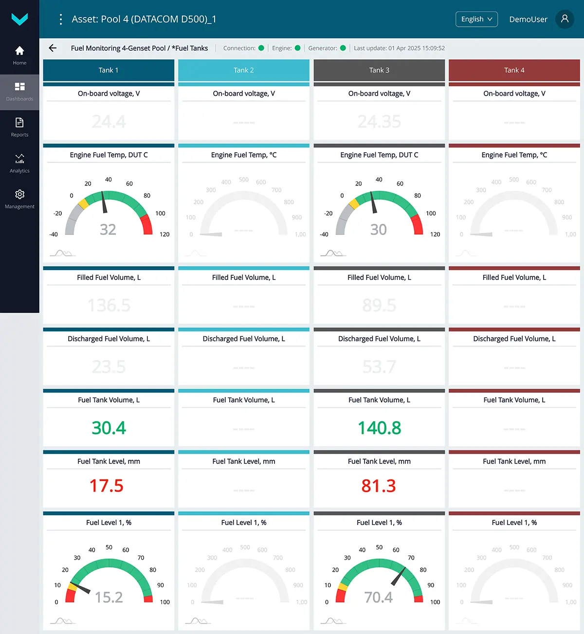
a) real-time display of information on the *Fuel Tanks dashboard
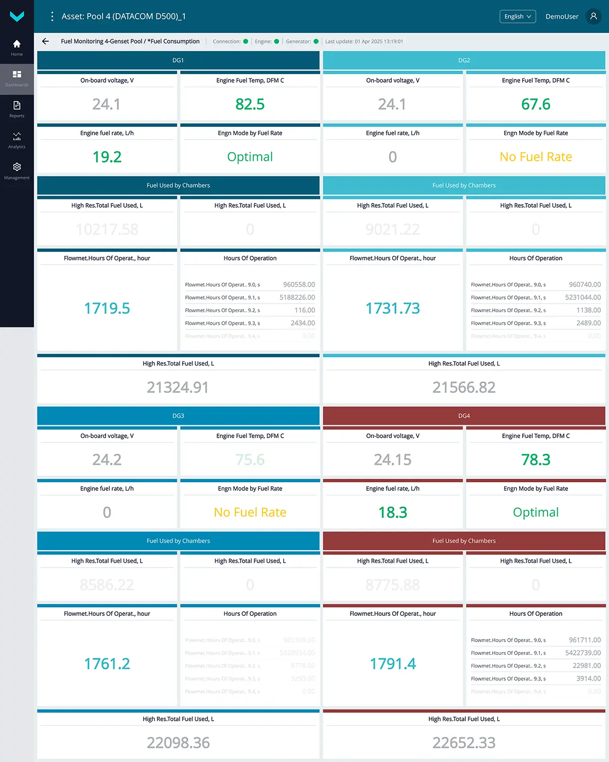
b) real-time display of information on the *Fuel consumption dashboard
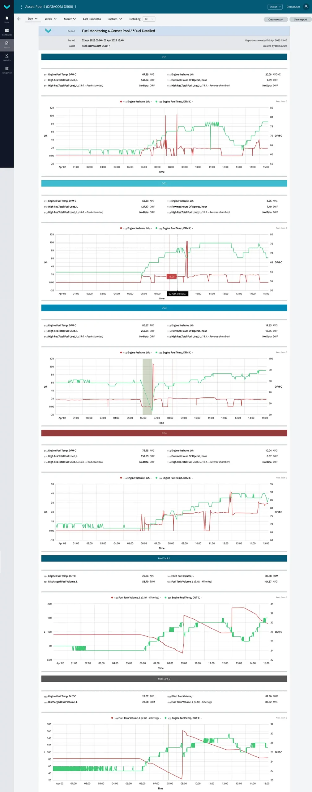
c) analytical report *Fuel Detailed for the “one-day” period
Figure 3 — Examples of default data display for the Fuel Monitoring Genset Pool task
1.4 Fuel Consumption High-Power DG #
Task class: 50.
Purpose:
Fuel Consumption High-Power DG — this task is designed for real-time monitoring or analysis over a selected period of detailed data on fuel level and volume in the tank, fuel temperature, as well as fuel consumption and engine runtime (total and by load modes, including supply and return lines in case of differential measurement) for high-power diesel generators (>600 kW).
Equipment used:
- DUT-E / DUT-E 2Bio / DUT-E S7 / DUT-E 2Bio S7 fuel level sensor – 1 pc.;
- DFM Marine / DFM Marine S7 fuel flow meter – 2 pcs.;
- CANUp 27 Genset telematics gateway – 1 pc.
Total keys: 50 pcs.
Preconfigured keys: 30 pcs. (see table 4).
Free keys: 20 pcs.
Table 4 — Preconfigured keys for the Fuel Consumption High-Power DG task
| Source network address | SPN and specifier (if applicable) |
Unit of measurement | Description |
| 101 | 96 Fuel Level 1 | % | Current value (in %) of the fuel level in the tank in relation to the level of the full tank. |
| 101 | 158 On-board voltage | V | Onboard voltage (from the ignition switch) based on data from the fuel level sensor. |
| 101 | 174 Engine Fuel Temp | °C | Current value of fuel temperature in the tank. |
| 111 | 174 Engine Fuel Temp | °C | Current value of fuel temperature in the flow meter measuring chamber (“Feed” line). |
| 112 | 174 Engine Fuel Temp | °C | Current value of fuel temperature in the flow meter measuring chamber (“Return” line). |
| 101 | 521023 Fuel Tank Level 2. Mathematical processing : 10. Filtering |
mm | Fuel level value in the tank, filtered by the specified time interval. |
| 101 | 521024 Fuel Tank Volume 2. Mathematical processing : 10. Filtering |
l | The value of the fuel volume in tank filtered according to the preset time interval. |
| 100 | 521055 Vehicle Power Supp.Volt. | V | Current onboard voltage value based on data from the telematics gateway. |
| 111 | 521171 Flowmet.Hours Of Operat. | s | Counter of total time of the flow meter operation within the whole range of loads. The counter is increasing from the date of flow meter production and cannot be reset by user (“Feed” line). |
| 112 | 521171 Flowmet.Hours Of Operat. | s | Counter of total time of the flow meter operation within the whole range of loads. The counter is increasing from the date of flow meter production and cannot be reset by user (“Return” line). |
| 111 | 521181 Engn Mode by Fuel Rate | No | Current operation mode of fuel consumer, correspondent to hourly rate of fuel consumption (applicable for one-chamber flow meter). For differential flow meter – current operation mode of fuel consumer, correspondent to hourly differential rate of fuel consumption. |
| 111 | 521267 Interference sens.count | pcs. | Number of detected tampering events involving the flow meter (“Feed” line). |
| 112 | 521267 Interference sens.count | pcs. | Number of detected tampering events involving the flow meter (“Return” line). |
| 101 | 521301 Filled Fuel Volume | l | Volume of fuel filled during a recorded “Fuelling” event. |
| 101 | 521302 Discharged Fuel Volume | l | Volume of fuel drained during a recorded “Fuel discharging” event. |
| 111 | 521310 Interference Duration | s | Duration of intervention in the flow meter operation when the “Interference” event is recorded (“Feed” line). |
| 112 | 521310 Interference Duration | s | Duration of intervention in the flow meter operation when the “Interference” event is recorded (“Return” line). |
| 111 | 521313 Engine fuel rate | m³/h | Hourly fuel consumption (“Feed” line). |
| 112 | 521313 Engine fuel rate | m³/h | Hourly fuel consumption (“Return” line). |
| 111 | 521313 Engine fuel rate 2. Mathematical processing : 15. Differential |
m³/h | Differential hourly fuel consumption, going through measuring chambers of Master-flow meter (“Feed” line) and Slave-flow meter (“Return” line). |
| 111 | 521314 Total Fuel Used | m³ | Counter of total fuel consumption by the engine within the whole range of loads. The counter is increasing from the date of flow meter production and cannot be reset by user (“Feed” line). |
| 112 | 521314 Total Fuel Used | m³ | Counter of total fuel consumption by the engine within the whole range of loads. The counter is increasing from the date of flow meter production and cannot be reset by user (“Return” line). |
| 111 | 521314 Total Fuel Used 2. Mathematical processing : 15. Differential |
m³ | Overall fuel consumption (differential mode) of the engine in all operation modes. The counter is increasing from the date of flow meter production and cannot be reset by user. |
| 111 | 521314 Total Fuel Used 2. Mathematical processing : 15. Differential 9. Movement mode based on fuel rate : 0. Idle |
m³ | Overall fuel consumption (differential mode) of the engine in “Idle” operation mode. The counter is increasing from the date of flow meter production and cannot be reset by user. |
| 111 | 521314 Total Fuel Used 2. Mathematical processing : 15. Differential 9. Movement mode based on fuel rate : 1. Optimal |
m³ | Overall fuel consumption (differential mode) of the engine in “Optimal” operation mode. The counter is increasing from the date of flow meter production and cannot be reset by user. |
| 111 | 521314 Total Fuel Used 2. Mathematical processing : 15. Differential 9. Movement mode based on fuel rate : 2. Overload |
m3 | Overall fuel consumption (differential mode) of the engine in “Overload” operation mode. The counter is increasing from the date of flow meter production and cannot be reset by user. |
| 111 | 521314 Total Fuel Used 2. Mathematical processing : 15. Differential 9. Movement mode based on fuel rate : 3. Cheating |
m3 | Overall fuel consumption (differential mode), which was higher than configured highest boundary of fuel consumption rate for installed flow meter. Increasing value of this counter may point on improper installation of flow meter or possible events of fuel theft. The counter is increasing from the date of flow meter production and cannot be reset by user. |
| 111 | 521314 Total Fuel Used 2. Mathematical processing : 15. Differential 28. Counter Type : 0. Clearable |
m3 | Overall fuel consumption (differential mode) of the engine in all operation modes. Counter is growing since the moment of previous reset by user. |
| 111 | 521331 Total Engine Fuel. High Resolution | m3 | Total fuel consumption with higher accuracy, which is increasing since the moment of flow meter manufacture. Counter cannot be reset by user (“Return” line). |
| 112 | 521331 Total Engine Fuel. High Resolution | m3 | Total fuel consumption with higher accuracy, which is increasing since the moment of flow meter manufacture. Counter cannot be reset by user (“Return” line). |
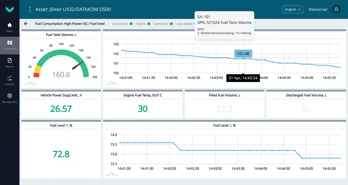
a) real-time display of information on the *Fuel level dashboard
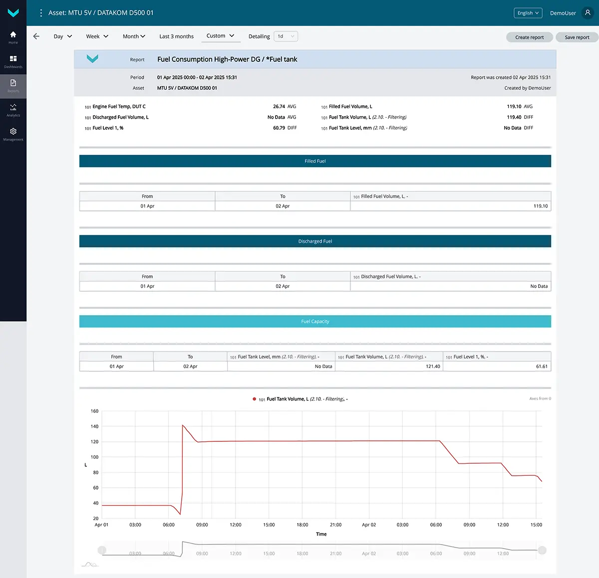
b) analytical report *Fuel tank for the “custom” period
Figure 4 — Examples of default data display for the Fuel Consumption High-Power DG task
1.5 Engine Monitoring #
Task class: 25.
Purpose:
Engine Monitoring — this task is intended for real-time monitoring or analysis over a selected period of key engine operation parameters of the diesel generator, based on data received from the standard CAN bus (SAE j1939) of the engine control unit (ECU).
Equipment used:
- CANCrocodile contactless reader – 1 pc.;
- CANUp 27 Genset telematics gateway – 1 pc.
Total keys: 25 pcs.
Preconfigured keys: 22 pcs. (see table 5).
Free keys: 3 pcs.
Table 5 — Preconfigured keys for the Engine Monitoring task
| Source network address | SPN and specifier (if applicable) |
Unit of measurement | Description |
| 0 | 98 Engine Oil Level | % | Current engine oil level. |
| 0 | 100 Oil pressure | kPa | Current engine oil pressure. |
| 0 | 106 Engn Air Intake Prs | kPa | Current engine intake manifold pressure. |
| 0 | 109 Engn Coolant Prs | kPa | Current engine coolant pressure. |
| 0 | 110 Coolant temp3. | °C | Current engine coolant temperature. |
| 0 | 111 Engine Coolant Lvl | % | Current engine coolant level. |
| 100 | 158 On-board voltage | V | Onboard voltage (from the ignition switch) based on data from the telematics gateway. |
| 0 | 158 On-board voltage | V | Onboard voltage (from the ignition switch) based on data from the onboard CAN bus. |
| 0 | 168 Battery Potent/Power In1 | V | Onboard voltage (primary power circuit voltage supplied by the battery or alternator). |
| 0 | 174 Engine Fuel Temp | °C | Current value of fuel temperature in the tank. |
| 0 | 175 Engn Oil Tmp | °C | Current engine oil temperature. |
| 0 | 176 Engn Turbocharg. Oil Tmp | °C | Current turbocharger oil temperature. |
| 0 | 183 Engine fuel rate | l/h | Hourly engine fuel consumption based on data from the onboard CAN bus. |
| 0 | 190 Engine RPM | rpm | Current engine crankshaft speed (RPM). |
| 100 | 521055 Vehicle Power Supp.Volt. | V | Current onboard voltage based on data from the telematics gateway. |
| 0 | 521211 Low Engine Oil Pressure | No | Alert for “Low engine oil pressure” event. |
| 0 | 521212 High Engine Oil Pressure | No | Alert for “High engine oil pressure” event. |
| 0 | 521213 Engine Overspeed | No | Alert for “Engine overspeed” event. |
| 0 | 521223 High Voltage | No | Alert for “Onboard voltage too high” event. |
| 0 | 521224 Low Voltage | No | Alert for “Onboard voltage too low” event |
| 100 | 521747 Engine Emergency Stop | No | Alert for “Emergency engine shutdown” event. |
| 100 | 521786 Fault | No | Alert for “Fault” event. |
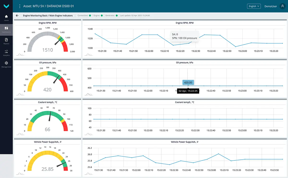
a) real-time display of information on the *Main Engine Indicators dashboard
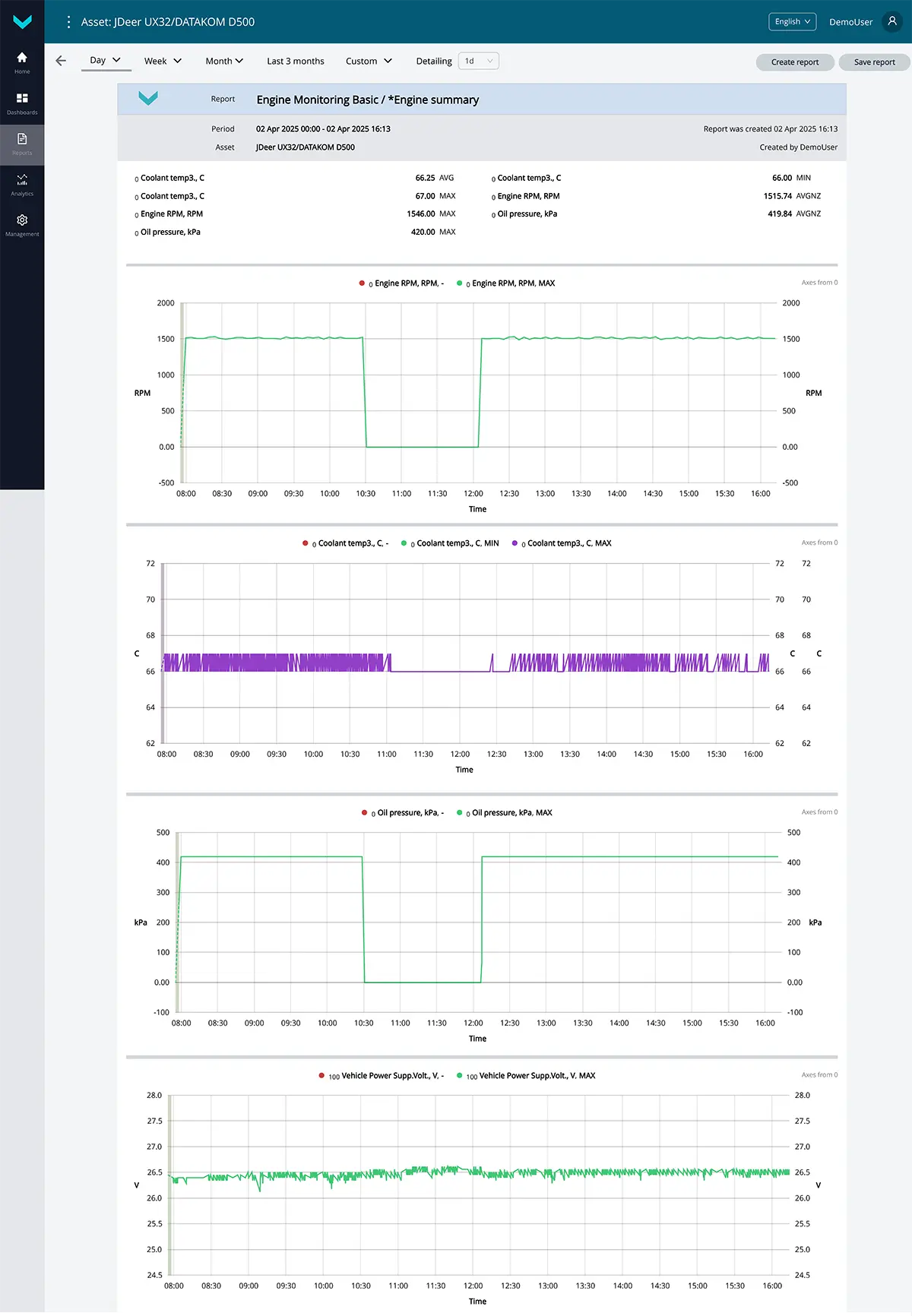
b) analytical report *Engine summary for the “one-day” period
Figure 5 — Examples of default data display for the Engine Monitoring task
1.6 Alternator Monitoring #
Task class: 50.
Purpose:
Alternator Monitoring — this task is designed for real-time monitoring or analysis over a selected period of detailed electrical parameters of the diesel generator alternator, based on data received from the genset control panel (controller).
Equipment used:
- CANUp 27 Genset telematics gateway – 1 pc.
Total keys: 50 pcs.
Preconfigured keys: 32 pcs. (see table 6).
Free keys: 18 pcs
Table 6 Preconfigured keys for the Alternator Monitoring task
| Source network address | SPN and specifier (if applicable) |
Unit of measurement | Description |
| 134 | 167 Battery voltage | V | Battery charging voltage (based on data from the control panel). |
| 100 | 167 Battery voltage | V | Battery charging voltage (based on data from the telematics gateway). |
| 134 | 589 Alternator Speed | rpm | Current generator rotational speed. |
| 134 | 2436 Average AC Frequency | Hz | Current generator frequency. |
| 134 | 2441 Phase AB AC RMS Voltage | V | Current generator voltage L1 (A) – L2(B) |
| 134 | 2442 Phase BC AC RMS Voltage | V | Current generator voltage L2 (B) – L3(C) |
| 134 | 2443 Phase CA AC RMS Voltage | V | Current generator voltage L3 (C) – L1(A) |
| 134 | 2445 A-N AC RMS Voltage | V | Current generator voltage L1(A) – N(Neutral) |
| 134 | 2446 B-N AC RMS Voltage | V | Current generator voltage L2(B) – N(Neutral) |
| 134 | 2447 C-N AC RMS Voltage | V | Current generator voltage L3(C) – N(Neutral) |
| 134 | 2448 Average AC RMS Current | A | Current generator current. |
| 134 | 2449 L1(A) AC RMS Current | A | Current generator current L1(A). |
| 134 | 2450 L2(B) AC RMS Current | A | Current generator current L2(B). |
| 134 | 2451 L3(C) AC RMS Current | A | Current generator current L3(C). |
| 134 | 2452 Total Real Power | Watt | Generator active power. |
| 134 | 2453 Phase A Real Power | Watt | Generator active power L1(A). |
| 134 | 2454 Phase B Real Power | Watt | Generator active power L2(B). |
| 134 | 2455 Phase C Real Power | Watt | Generator active power L3(C). |
| 134 | 2456 Total Reactive Power | VAr | Generator reactive power. |
| 134 | 2457 Phase A Reactive Pwr | VAr | Generator reactive power L1(A). |
| 134 | 2458 Phase B Reactive Pwr | VAr | Generator reactive power L2(B). |
| 134 | 2459 Phase C Reactive Pwr | VAr | Generator reactive power L3(C). |
| 134 | 2460 Total Apparent Power | VA | Generator apparent power. |
| 134 | 2461 L1(A) Apparent Power | VA | Generator apparent power L1 (A). |
| 134 | 2462 L2(B) Apparent Power | VA | Generator apparent power L2 (B). |
| 134 | 2463 L3(C) Apparent Power | VA | Generator apparent power L3 (C). |
| 134 | 2464 Overall Power Factor | No | Power factor (COS φ) |
| 134 | 2465 Phase A Power Factor | No | Generator Phase A power factor. |
| 134 | 2466 Phase B Power Factor | No | Generator Phase B power factor. |
| 134 | 2467 Phase C Power Factor | No | Generator Phase C power factor. |
| 134 | 2468 Total kW Hours Export | kWh | Amount of energy generated. |
| 134 | 3590 Generator Total Percent kW | % | Total generator load percentage, kW. |
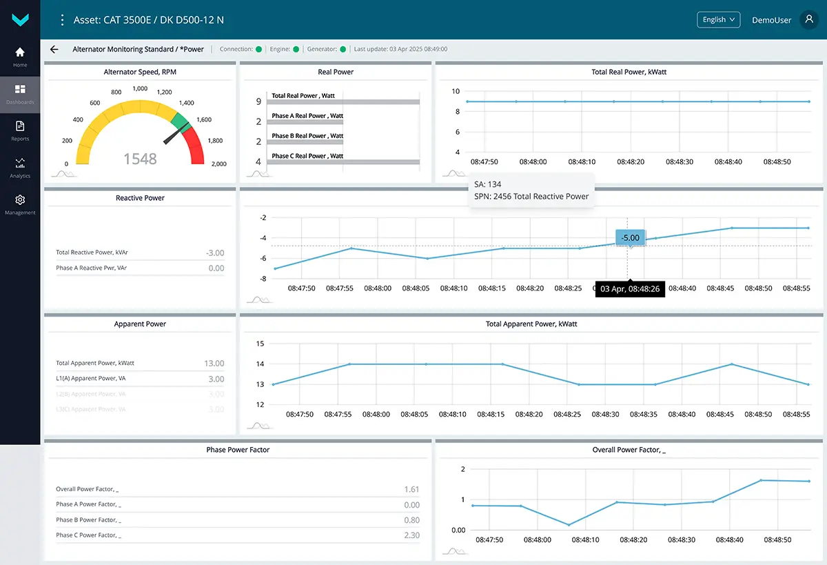
a) real-time display of information on the *Power dashboard
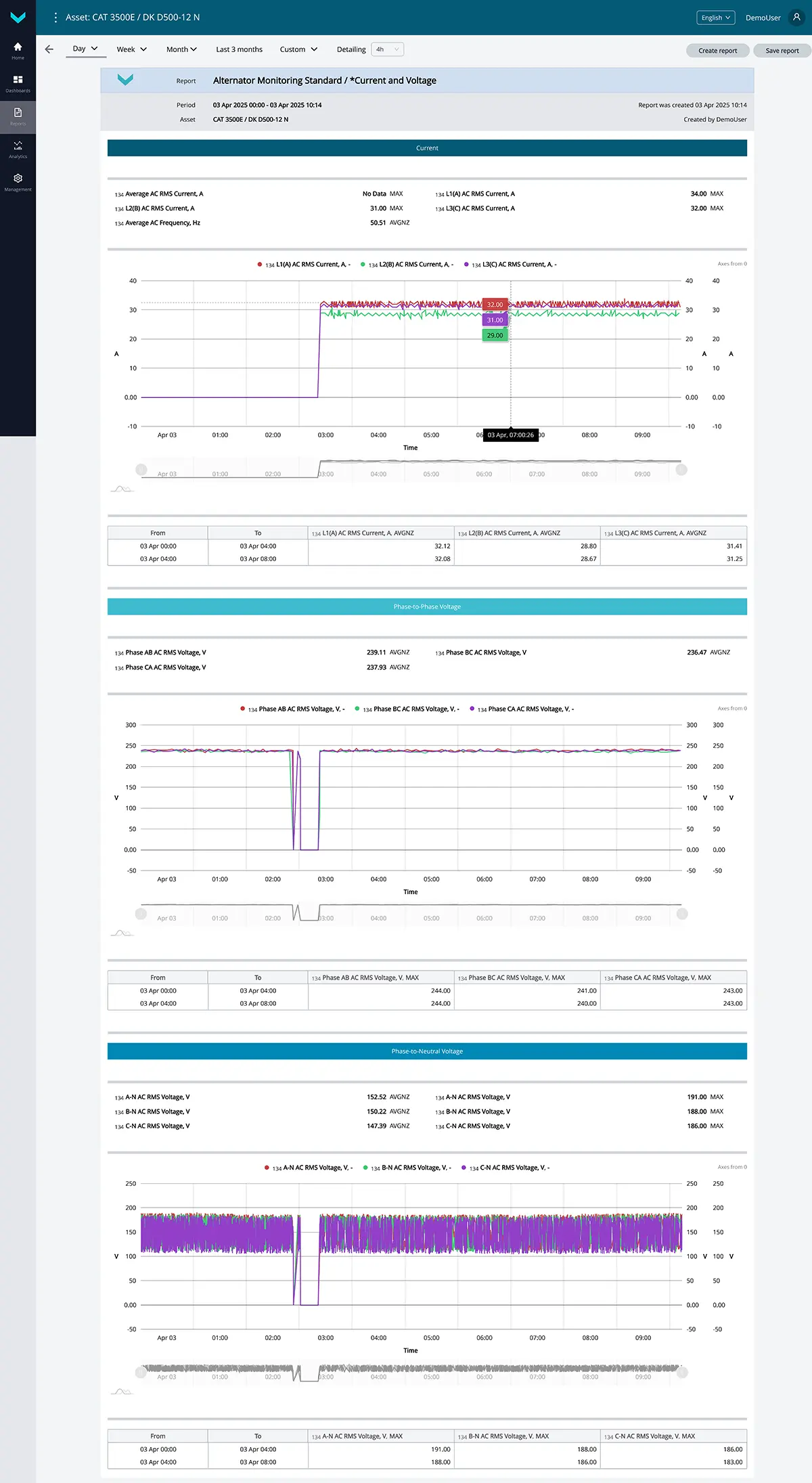
b) analytical report *Current and Voltage for the “one-day” period
Figure 6 — Examples of default data display for the Alternator Monitoring task
1.7 Remote Genset Control #
Task class: 25.
Purpose:
Remote Genset Control — this task is intended for remote control of the diesel generator (for configuration, start/stop operations, fault reset, and other actions) via Modbus RTU register write commands to the control panel (controller), such as DeepSea or DATACOM.
Equipment used:
- DUT-E / DUT-E 2Bio / DUT-E S7 / DUT-E 2Bio S7 fuel level sensor – 1 pc.;
- CANUp 27 Genset telematics gateway – 1 pc.
Total keys: 25 pcs.
Preconfigured keys: 13 pcs. (see table 7).
Free keys: 12 pcs.
Table 7 — Preconfigured keys for the Remote Genset Control task
| Source network address | SPN and specifier (if applicable) |
Unit of measurement | Description |
| 0 | 110 Coolant temp3. | °C | Current engine coolant temperature. |
| 100 | 158 On-board voltage | V | Onboard voltage (from the ignition switch) based on data from the telematics gateway. |
| 134 | 2441 Phase AB AC RMS Voltage | V | Current generator voltage L1 (A) – L2(B). |
| 134 | 2442 Phase BC AC RMS Voltage | V | Current generator voltage L2 (B) – L3(C). |
| 134 | 2443 Phase CA AC RMS Voltage | V | Current generator voltage L3 (C) – L1(A). |
| 134 | 2449 L1(A) AC RMS Current | A | Current generator current L1(A). |
| 134 | 2450 L2(B) AC RMS Current | A | Current generator current L2(B). |
| 134 | 2451 L3(C) AC RMS Current | A | Current generator current L3(C). |
| 134 | 2452 Total Real Power | Watt | Generator active power. |
| 134 | 2453 Phase A Real Power | Watt | Generator active power L1(A). |
| 134 | 2454 Phase B Real Power | Watt | Generator active power L2(B). |
| 134 | 2455 Phase C Real Power | Watt | Generator active power L3(C). |
| 101 | 521024 Fuel Tank Volume 2. Mathematical processing : 10. Filtering |
l | The value of the fuel volume in tank filtered according to the preset time interval. |
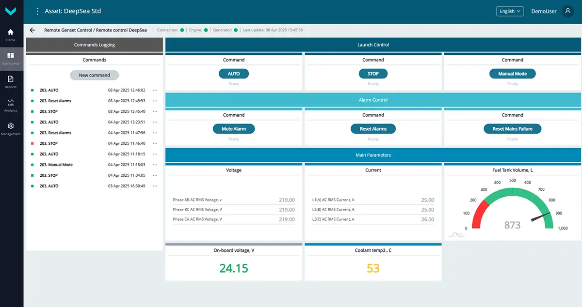
a) real-time display of information on the *Remote control DeepSea dashboard
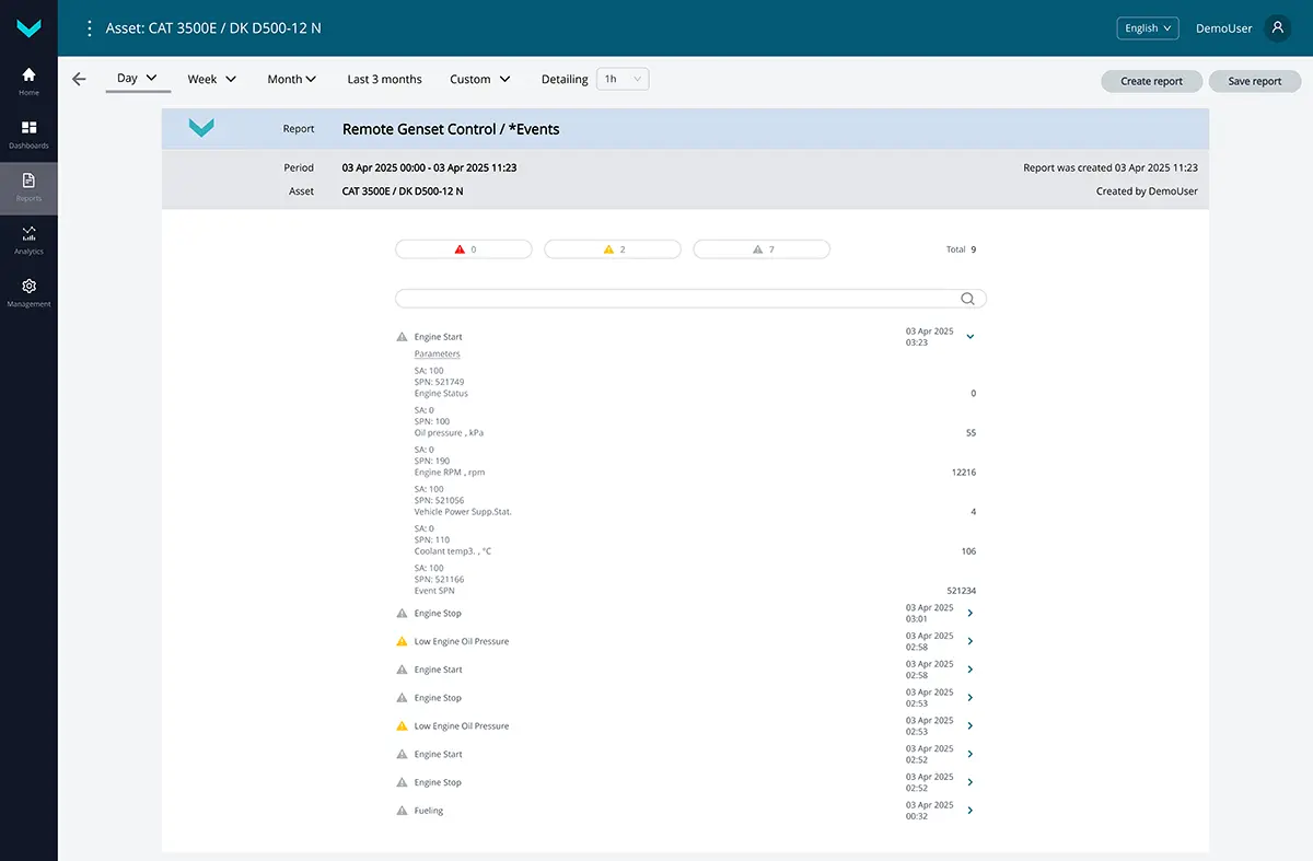
b) analytical report *Events for the “one-day” period
Figure 7 — Examples of default data display for the Remote Genset Control task
1.8 System Self-Diagnostics #
Task class: 50.
Purpose:
System Self-Diagnostics — this task is activated by default for each asset and is used for real-time monitoring or analysis over a selected period to assess the performance quality of the genset’s onboard equipment.
Equipment used:
- DUT-E / DUT-E 2Bio / DUT-E S7 / DUT-E 2Bio S7 fuel level sensors – up to 8 pcs.;
- DFM / DFM D / DFM S7 / DFM D S7 / DFM Marine / DFM Marine S7
fuel flow meters – up to 8 pcs.; - MasterCAN Display 35 CAN j1939/S6 displays – up to 2 pcs.;
- MasterCAN DAC15 digital-to-analog converter – 1 pc.;
- CANUp 27 Genset telematics gateway – 1 pc.
Total keys: 50 pcs.
Preconfigured keys: 47 pcs. (see table 8).
Free keys: 3 pcs.
Table 8 — Preconfigured keys for the System Self-Diagnostics task
| Source network address | SPN and specifier (if applicable) |
Unit of measurement | Description |
| 100 | 158 On-board voltage | V | Onboard voltage (from the ignition switch) based on data from the telematics gateway. |
| 100 | 165 Compass Bearing | degrees | Movement direction of the asset, defined according to GNSS data. |
| 100 | 580 Altitude | m | Height of present asset location above the sea level, defined according to GNSS data. |
| 100 | 584 Latitude | degrees | Geographical coordinates of latitude of present location of the asset, defined according to GNSS data. |
| 100 | 585 Longitude | degrees | Geographical coordinates of longitude of present location of the asset, defined according to GNSS data. |
| 100 | 521050 Battery Level State | No | Current charge status of inbuilt battery of the telematics gateway: – fully charged; – charging; – cannot define battery status; – battery is not available. |
| 100 | 521055 Vehicle Power Supp.Volt. | V | Current onboard voltage. |
| 100 | 521056 Vehicle Power Supp.Stat. | No | Current mode of ON in accordance with user-defined borders of ON voltage levels of asset (Off/Lowe level/Accumulator/Starter/Generator/High level). |
| 100 | 521072 Reports Counter 21. Priority : 2. Information |
pcs. | Current number of registered reports on informational events (for example – “Ignition On/Off”, “Satellites detected/lost”, “GPRS is available/not available”). |
| 100 | 521072 Reports Counter 21. Priority : 0. Emergency |
pcs. | Current number of registered reports on emergency events (for example – “Alarm”). |
| 100 | 521072 Reports Counter 21. Priority : 1. Important |
pcs. | Current number of registered reports on important events (for example – “Fuel discharge”, “Fuelling”). |
| 100 | 521090 HDOP | No | Value of HDOP – coefficient that characterizes accuracy of the current location defining of the asset in the horizontal plane. HDOP value can vary in range from 1 (maximum accuracy) to 50 (minimum accuracy). |
| 100 | 521116 Unit Hours Of Operation1 | s | Counter of summarized working time of the telematics gateway since its production moment. The user cannot reset this counter himself. |
| 100 | 521116 Unit Hours Of Operation1 16. Working time from power supply : 1. Battery |
s | Counter of summarized working time of the telematics gateway using the inbuilt accumulator battery (in case there is no power supply from the external source) since its production moment. The user cannot reset this counter himself. |
| 100 | 521118 Unit Reset Counter 30. Appearance Source : 0. Software |
pcs. | Counter of sensor’s processor restarts at a time when the power is On or there is an impact of conducted interferences of the asset’s on-board network. Restarts accounting is carried out since production date of the telematics gateway. The user cannot reset this counter himself. |
| 100 | 521118 Unit Reset Counter 30. Appearance Source : 1. Hardware |
pcs. | Counter of the number of telematics gateway processor restarts in case of power supply failure (onboard circuit outage and complete battery discharge) or in case of the unit inbuilt software failure. The counting of restarts is conducted from the moment of telematics gateway delivery from the factory. The user cannot reset this counter himself. |
| 100 | 521128 Satellites Quantity | pcs. | Number of visible navigation satellites. |
| 100 | 521129 Unit Power Status | No | Current power-supply status of the telematics gateway: – powered from embedded power source; – powered from on-board electrical system; – power is off; – power-supply status is not available/not supported by this device. |
| 100 | 521134 GNSS Receiver Status | No | Status of serviceability of built-in navigation receiver telematics gateway (On/Error). |
| 100 | 521135 GNSS Antenna Status | No | Connection status of built-in navigation antenna telematics gateway. Status “Connected” is always displayed for GNSS antenna. |
| 100 | 521144 AVL Connection Counter | pcs. | Counter of GPRS modem of the telematics gateway connections to AVL server. User can reset values of all counters if it is necessary. |
| 100 | 521145 AVL Connect.Fail.Counter | pcs. | Counter of the telematics gateway GPRS modem connection errors while connecting to AVL server. User can reset values of all counters if it is necessary. |
| 100 | 521146 AVL Disconnect. Counter | pcs. | Counter of the telematics gateway GPRS modem disconnections from AVL server. User can reset values of all counters if it is necessary. |
| 100 | 521176 AVL Authent.Count. | pcs. | Counter of successful authentications of the telematics gateway at AVL server. User can reset values of all counters if it is necessary. |
| 100 | 521177 AVL Authent.Fail.Count. | pcs. | Counter of authentication errors of the telematics gateway at AVL server. User can reset values of all counters if it is necessary. |
| 100 | 521178 RSSI | dBm | Level of signal strength (on a logarithmic scale) received by GPRS modem receiver of the telematics gateway. Produced range: from -52 to -115 dBm. |
| 100 | 521334 GSM Network Mode | No | Cellular communication standard which is currently used by the telematics gateway inbult GSM modem (2G/3G/4G). |
| 100 | 521488 Unit DTCs Mask | No | Telematics gateway fault mask. |
| 101 | 521488 Unit DTCs Mask | No | Fuel level sensor No. 1 fault mask. |
| 102 | 521488 Unit DTCs Mask | No | Fuel level sensor No. 2 fault mask. |
| 103 | 521488 Unit DTCs Mask | No | Fuel level sensor No. 3 fault mask. |
| 104 | 521488 Unit DTCs Mask | No | Fuel level sensor No. 4 fault mask. |
| 105 | 521488 Unit DTCs Mask | No | Fuel level sensor No. 5 fault mask. |
| 106 | 521488 Unit DTCs Mask | No | Fuel level sensor No. 6 fault mask. |
| 107 | 521488 Unit DTCs Mask | No | Fuel level sensor No. 7 fault mask. |
| 108 | 521488 Unit DTCs Mask | No | Fuel level sensor No. 8 fault mask. |
| 111 | 521488 Unit DTCs Mask | No | Fuel flow meter No. 1 fault mask. |
| 112 | 521488 Unit DTCs Mask | No | Fuel flow meter No. 2 fault mask. |
| 113 | 521488 Unit DTCs Mask | No | Fuel flow meter No. 3 fault mask. |
| 114 | 521488 Unit DTCs Mask | No | Fuel flow meter No. 4 fault mask. |
| 115 | 521488 Unit DTCs Mask | No | Fuel flow meter No. 5 fault mask. |
| 116 | 521488 Unit DTCs Mask | No | Fuel flow meter No. 6 fault mask. |
| 117 | 521488 Unit DTCs Mask | No | Fuel flow meter No. 7 fault mask. |
| 118 | 521488 Unit DTCs Mask | No | Fuel flow meter No. 8 fault mask. |
| 109 | 521488 Unit DTCs Mask | No | CAN display No. 1 fault mask. |
| 110 | 521488 Unit DTCs Mask | No | CAN display No. 2 fault mask. |
| 126 | 521488 Unit DTCs Mask | No | Digital-to-analog converter fault mask. |
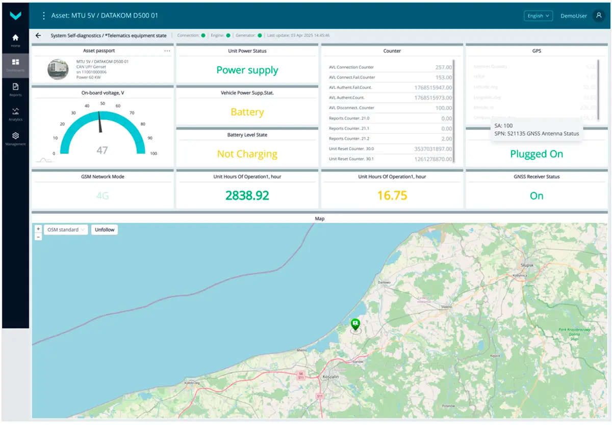
a) real-time display of information on the *Telematics equipment state dashboard
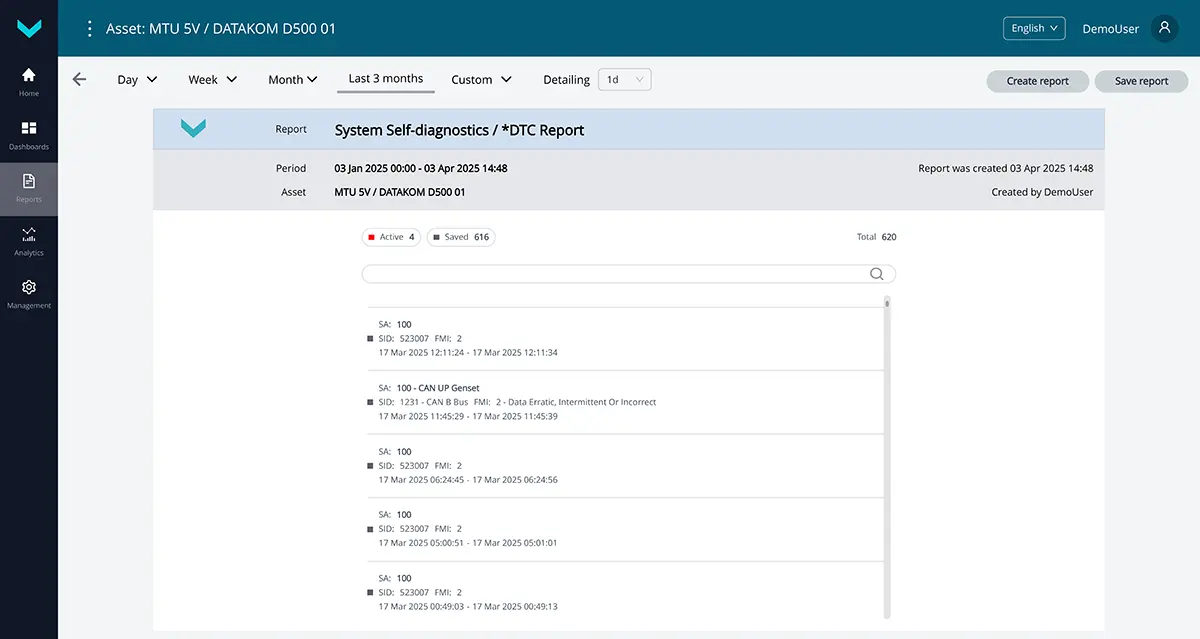
b) analytical report *DTC Report for the “last 3 months” period
Figure 8 — Examples of default data display for the System Self-Diagnostics task
1.9 Genset Maintenance #
Task class: 25.
Purpose:
Genset Maintenance — this task is intended for generating reminders about scheduled maintenance of diesel generator components, based on predefined runtime or resource usage thresholds.
Components include functional parts of the genset (diesel engine, alternator, cooling, lubrication, fuel supply, and power systems), as well as onboard equipment (telematics gateway, fuel flow meters, etc.).
Equipment used:
- CANCrocodile contactless reader – 1 pc.;
- DFM / DFM D / DFM S7 / DFM D S7 fuel flow meter – 1 pc.;
- CANUp 27 Genset telematics gateway – 1 pc.
Total keys: 25 pcs.
Preconfigured keys: 21 pcs. (see table 9).
Free keys: 4 pcs.
Table 9 — Preconfigured keys for the Genset Maintenance task
| Source network address | SPN and specifier (if applicable) |
Unit of measurement | Description |
| 100 | 100 Oil pressure | kPa | Current engine oil pressure based on data from the telematics gateway. |
| 0 | 100 Oil pressure | kPa | Current engine oil pressure based on data from the onboard CAN bus. |
| 100 | 110 Coolant temp3. | °C | Current engine coolant temperature based on data from the telematics gateway. |
| 0 | 110 Coolant temp3. | °C | Current engine coolant temperature based on data from the onboard CAN bus. |
| 100 | 158 On-board voltage | V | Onboard voltage (from the ignition switch) based on data from the telematics gateway. |
| 0 | 158 On-board voltage | V | Onboard voltage (from the ignition switch) based on data from the onboard CAN bus. |
| 100 | 190 Engine RPM | rpm | Current engine crankshaft speed (RPM) based on data from the telematics gateway. |
| 0 | 190 Engine RPM | rpm | Current engine crankshaft speed (RPM) based on data from the onboard CAN bus. |
| 100 | 521001 Tot.Engn Starts Count. | pcs. | Counter of total number of the engine starts which increments in case of any rpm. Counter can be reset by user. |
| 100 | 521006 Exceed.Start.Time Count. | pcs. | Counter of total number of all engine starts performed with exceeding the maximum time of starter uninterrupted operation. Counter increment starts from the moment the telematics gateway is manufactured and cannot be reset by user. |
| 100 | 521007 Engn Start Fail. Count. | pcs. | Counter of total number of unsuccessful engine starts (i.e. when an attempt of engine start is recorded, but engine is not started). Counter increment starts from the moment the telematics gateway is manufactured and cannot be reset by user. |
| 100 | 521050 Battery Level State | No | Current charge status of inbuilt battery of the telematics gateway: – fully charged; – charging; – cannot define battery status; – battery is not available. |
| 100 | 521055 Vehicle Power Supp.Volt. | V | Current onboard voltage. |
| 100 | 521072 Reports Counter | pcs. | Displays current number of registered reports. |
| 100 | 521072 Reports Counter 21. Priority : 0. Emergency |
pcs. | Displays current number of registered reports on emergency events (for example – “Alarm”). |
| 100 | 521076 Vehicle Power Supp.Pres. | No | Current onboard power state (On/Off) based on the user-defined onboard voltage cutoff threshold. |
| 100 | 521116 Unit Hours Of Operation1 | s | Counter of total operation time of the telematics gateway from embedded battery since installation to asset. The counter cannot be reset by user. |
| 111 | 521116 Unit Hours Of Operation1 | s | Counter of total operation time of the flow meter from embedded battery since installation to asset. The counter cannot be reset by user. |
| 100 | 521190 Engn Hours Of Operation | s | Counter of total time of the engine operation within the whole range of load, including the “Idle” mode of engine operation. Counter can be reset by user. |
| 100 | 521488 Unit DTCs Mask | No | Telematics gateway fault mask. |
| 100 | 521749 Engine Status | No | Current engine status (Stop/Start/Runnning) is displayed; it is automatically defined, depending on current parameters received in the priority descending order from the following sources: 1) Engine rpm from onboard CAN-bus; 2) Input signal from frequency input; 3) Onboard circuit status. |
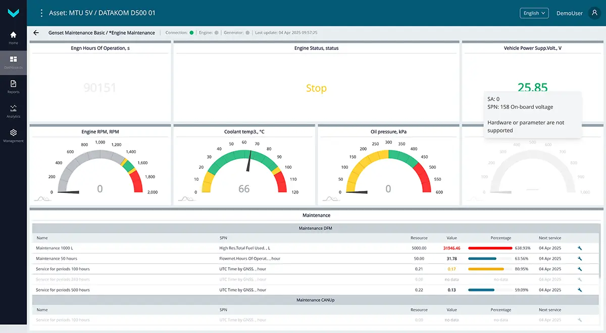
a) real-time display of information on the *Engine Maintenance dashboard
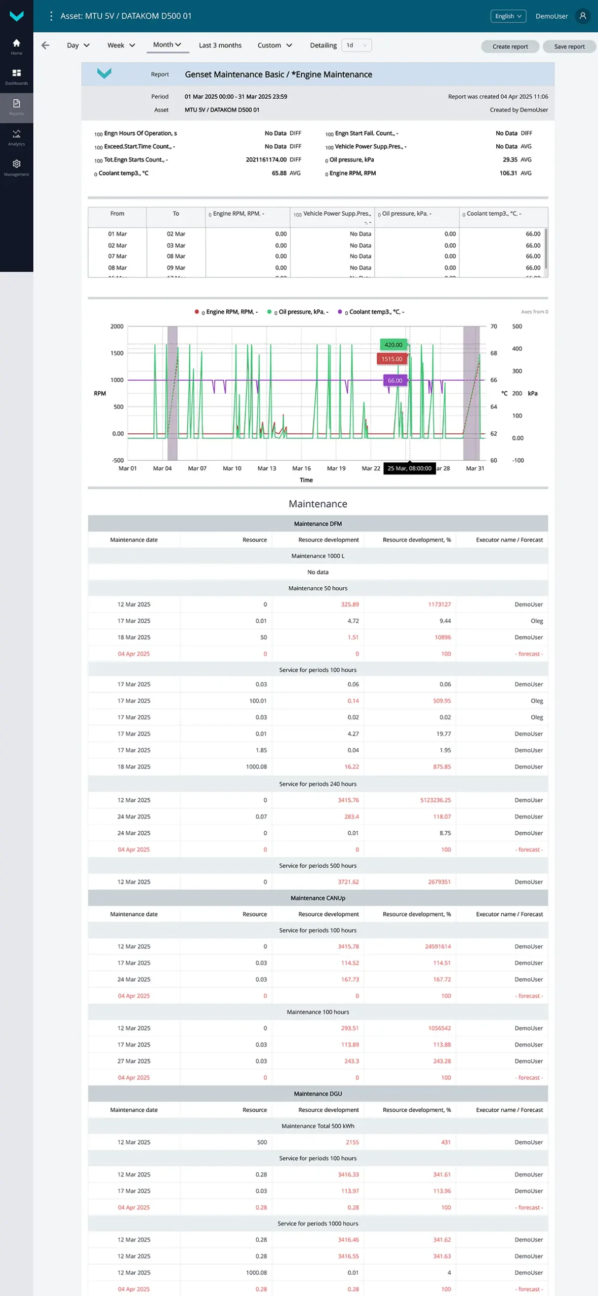
b) analytical report *Engine Maintenance for the “one-month” period
Figure 9 — Examples of default data display for the Genset Maintenance task
1.10 Location Tracking #
Task class: 25.
Purpose:
Location Tracking — this task is used for real-time map-based tracking of the exact location and movement route of mobile assets, as well as for detailed trip data analysis over a selected time period.
Equipment used:
- CANUp 27 Genset telematics gateway – 1 pc.
Total keys: 25 pcs.
Preconfigured keys: 11 pcs. (see table 10).
Free keys: 14 pcs.
Table 10 — Preconfigured keys for the Location Tracking task
| Source network address | SPN and specifier (if applicable) |
Unit of measurement | Description |
| 125 | 84 Vehicle Speed, Wheel | km/h | Current speed of the mobile asset, determined by wheel speed sensor signals. |
| 125 | 182 Engine Trip Fuel | l | Fuel consumed during a trip, automatically calculated based on hourly fuel rate (183 Engine fuel rate). Trip start and end are determined by the activation/deactivation of the onboard power supply. The minimum increment for trip fuel consumption is 0.5 liters. |
| 125 | 183 Engine fuel rate | l/h | Hourly engine fuel consumption based on data from the onboard CAN bus. |
| 100 | 580 Altitude | m | Height of present asset location above the sea level, defined according to GNSS data. |
| 100 | 584 Latitude | degrees | Geographical coordinates of latitude of present location of the asset, defined according to GNSS data. |
| 100 | 585 Longitude | degrees | Geographical coordinates of longitude of present location of the asset, defined according to GNSS data. |
| 238 | 918 Trip Distance HR | km | Distance traveled by the mobile asset during a single trip, determined with enhanced accuracy. |
| 100 | 521090 HDOP | No | Value of HDOP – coefficient that characterizes accuracy of the current location defining of the asset in the horizontal plane. HDOP value can vary in range from 1 (maximum accuracy) to 50 (minimum accuracy). |
| 100 | 521126 Distance by GNSS | m | Total distance traveled by the mobile asset since the installation of the telematics gateway. This counter can be reset by the user. |
| 100 | 521128 Satellites Quantity | pcs. | Current number of visible navigation satellites. |
| 100 | 521155 UTC Time by GNSS | s | Current time in UTC format, determined from GNSS data. |
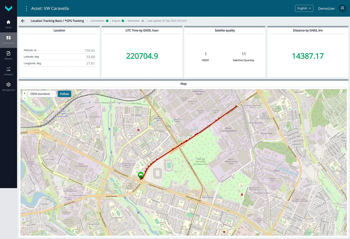
a) real-time display of information on the *GPS Tracking dashboard
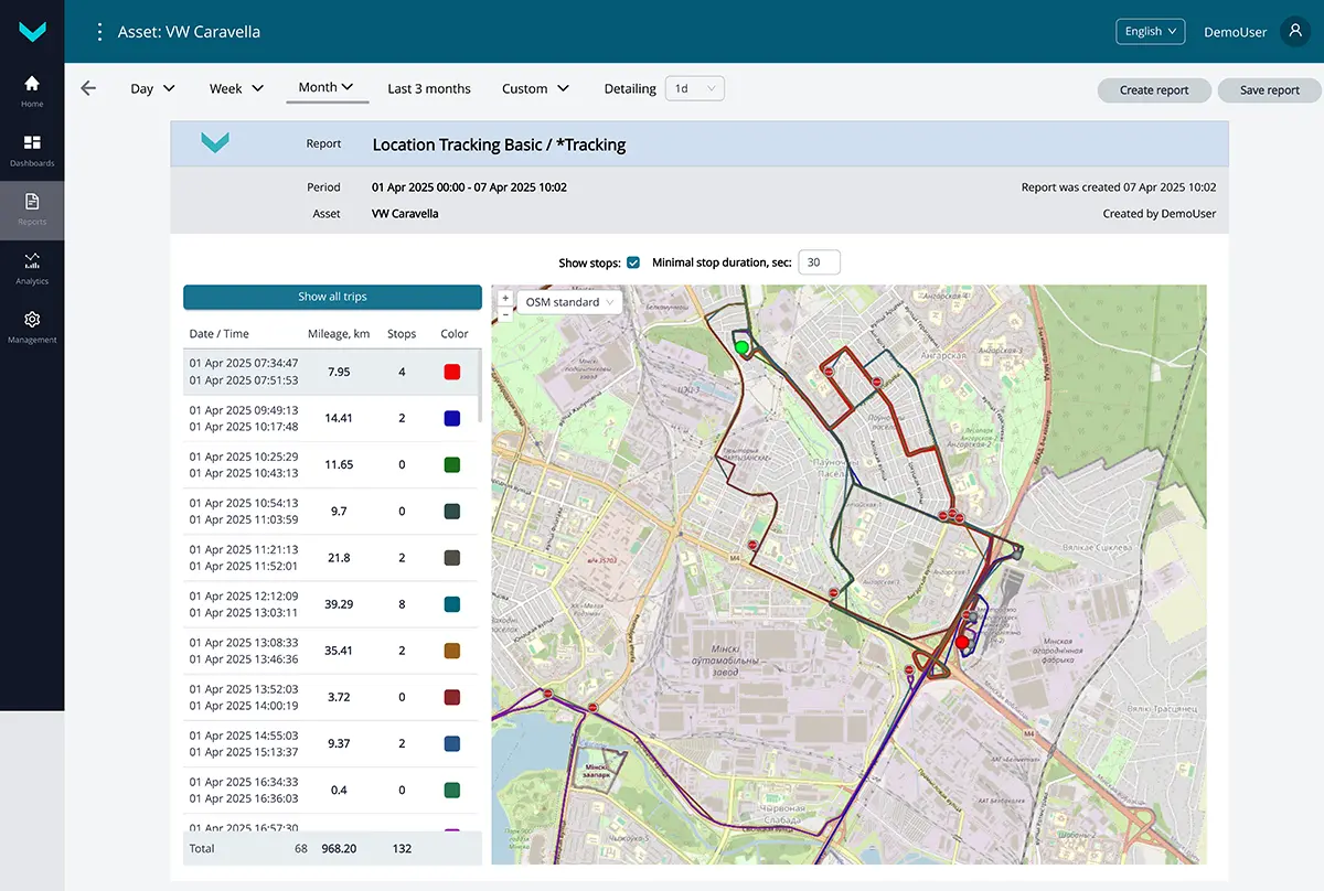
b) analytical report *Tracking for the “one-month” period
Figure 10 — Examples of default data display for the Location Tracking task
2 Tasks for monitoring gensets groups #
2.1 Group. Alternator Monitoring #
Task class: 50.
Purpose:
Group. Alternator Monitoring — this task is intended for real-time monitoring or analysis over a selected period of detailed electrical parameters of alternators in a diesel generator group, based on data received from the corresponding genset control panels (controllers).
Equipment used:
- CANUp 27 Genset telematics gateways – up to 20 pcs.
Total keys: 50 pcs.
Preconfigured keys: 26 pcs. (see table 11).
Free keys: 24 pcs.
Table 11 — Preconfigured keys for the Group. Alternator Monitoring task
| Source network address* | SPN and specifier (if applicable) |
Unit of measurement | Description |
| 1000 | 589 Alternator Speed | rpm | Current alternator rotation speed value for each genset in the group. |
| 1000 | 2436 Average AC Frequency | Hz | Current frequency value of each alternator for every genset in the group. |
| 1000 | 2441 Phase AB AC RMS Voltage | V | Current generator voltage value L1 (A) – L2 (B) for each genset in the group. |
| 1000 | 2442 Phase BC AC RMS Voltage | V | Current generator voltage value L2 (B) – L3 (C) for each genset in the group. |
| 1000 | 2443 Phase CA AC RMS Voltage | V | Current generator voltage value L3 (C) – L1 (A) for each genset in the group. |
| 1000 | 2448 Average AC RMS Current | A | Current generator current value for each genset in the group. |
| 1000 | 2449 L1(A) AC RMS Current | A | Current generator current value on L1 (A) for each genset in the group. |
| 1000 | 2450 L2(B) AC RMS Current | A | Current generator current value on L2 (B) for each genset in the group. |
| 1000 | 2451 L3(C) AC RMS Current | A | Current generator current value on L3 (C) for each genset in the group. |
| 1000 | 2452 Total Real Power | Watt | Active power of the generator for each genset in the group. |
| 1000 | 2453 Phase A Real Power | Watt | Active power of generator phase L1 (A) for each genset in the group. |
| 1000 | 2454 Phase B Real Power | Watt | Active power of generator phase L2 (B) for each genset in the group. |
| 1000 | 2455 Phase C Real Power | Watt | Active power of generator phase L3 (C) for each genset in the group. |
| 1000 | 2456 Total Reactive Power | VAr | Reactive power of the generator for each genset in the group. |
| 1000 | 2457 Phase A Reactive Pwr | VAr | Reactive power of generator phase L1 (A) for each genset in the group. |
| 1000 | 2458 Phase B Reactive Pwr | VAr | Reactive power of generator phase L2 (B) for each genset in the group. |
| 1000 | 2459 Phase C Reactive Pwr | VAr | Reactive power of generator phase L3 (C) for each genset in the group. |
| 1000 | 2460 Total Apparent Power | VA | Apparent power of the generator for each genset in the group. |
| 1000 | 2461 L1(A) Apparent Power | VA | Apparent power of generator phase L1 (A) for each genset in the group. |
| 1000 | 2462 L2(B) Apparent Power | VA | Apparent power of generator phase L2 (B) for each genset in the group. |
| 1000 | 2463 L3(C) Apparent Power | VA | Apparent power of generator phase L3 (C) for each genset in the group. |
| 1000 | 2464 Overall Power Factor | No | Power factor (COS φ) of the generator for each genset in the group. |
| 1000 | 2465 Phase A Power Factor | No | Power factor of generator phase A for each genset in the group. |
| 1000 | 2466 Phase B Power Factor | No | Power factor of generator phase B for each genset in the group. |
| 1000 | 2467 Phase C Power Factor | No | Power factor of generator phase C for each genset in the group. |
| 1000 | 2468 Total kW Hours Export | kWh | Amount of energy generated by the generator for each genset in the group. |
| * The source address (SA) of each key used in group tasks is always set to 1000, regardless of the source addresses of similar keys for individual assets within the group. |
|||
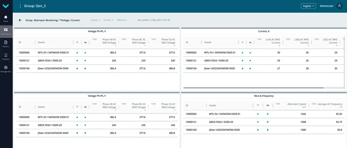
a) real-time display of information on the *Voltage / Current dashboard
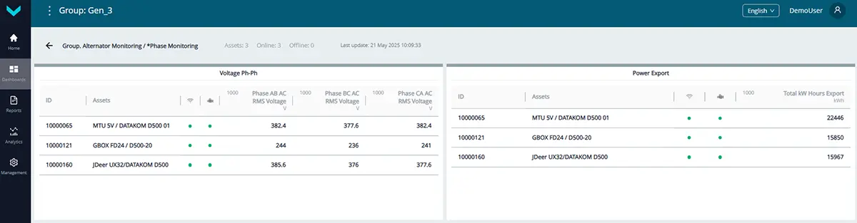
real-time display of information on the *Phase Monitoring dashboard
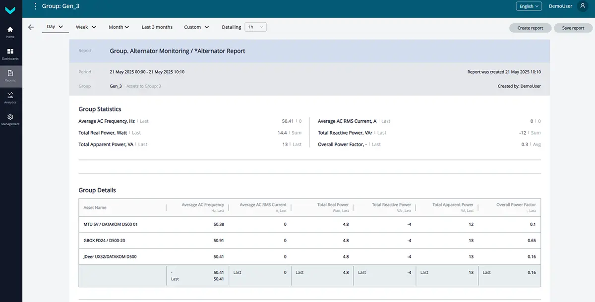
c) analytical report *Alternator Report for the “one-day” period
Figure 11 — Examples of default data display for the Group. Alternator Monitoring task
2.2 Group. Engine Monitoring #
Task class: 25.
Purpose:
Group. Engine Monitoring — this task is intended for real-time monitoring or analysis over a selected period of key engine operation parameters for a group of gensets, based on data received from the corresponding standard CAN buses (SAE j1939) of the engine control units (ECUs).
Equipment used:
- CANCrocodile contactless reader – up to 20 pcs.;
- CANUp 27 Genset telematics gateways – up to 20 pcs.
Total keys: 25 pcs.
Preconfigured keys: 10 pcs. (see table 12).
Free keys: 15 pcs.
Table 12 — Preconfigured keys for the Group. Engine Monitoring task
| Source network address* | SPN and specifier (if applicable) |
Unit of measurement | Description |
| 1000 | 98 Engine Oil Level | % | Current engine oil level value for each genset in the group. |
| 1000 | 100 Oil pressure | kPa | Current engine oil pressure value for each genset in the group. |
| 1000 | 110 Coolant temp3. | °C | Current engine coolant temperature value for each genset in the group. |
| 1000 | 111 Engine Coolant Lvl | % | Current engine coolant level value for each genset in the group. |
| 1000 | 173 Engn Exhst Gas Tmp | °C | Current exhaust gas temperature value for each genset in the group. |
| 1000 | 175 Engn Oil Tmp | °C | Current engine oil temperature value for each genset in the group. |
| 1000 | 190 Engine RPM | rpm | Current engine crankshaft speed value for each genset in the group. |
| 1000 | 247 Engine hours | h | Total engine runtime hours for each genset in the group. |
| 1000 | 3543 Engine Operating State | No | Current engine operating status (Off/Starting/Running/Stopping/Idle/Start Error) for each genset in the group. |
| 1000 | 521300 Event Date/Time | s | Date and time of the event recorded in the ECU (e.g., DTC activation, engine start/stop, overtemperature threshold exceeded, etc.) for each genset in the group. |
| * The source address (SA) of each key used in group tasks is always set to 1000, regardless of the source addresses of similar keys for individual assets within the group. |
|||
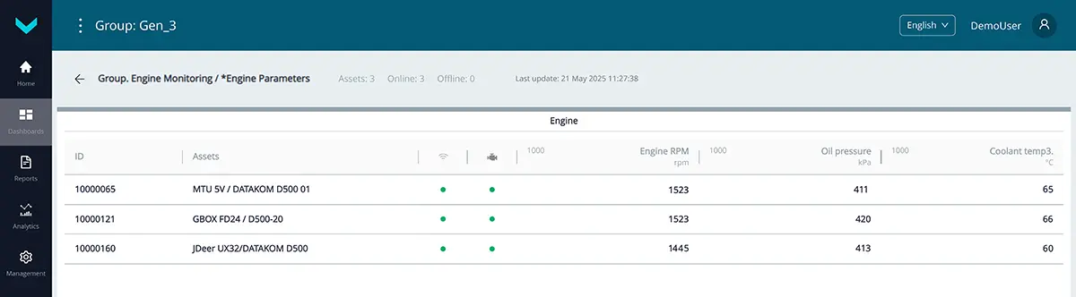
a) real-time display of information on the *Engine Parameters dashboard
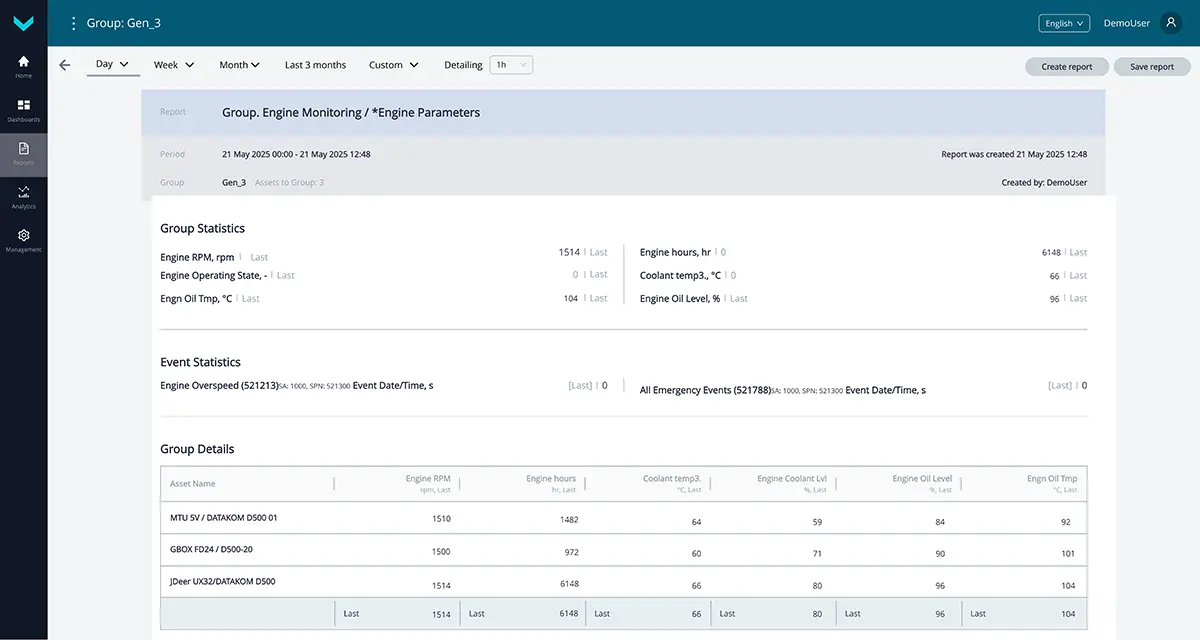
b) analytical report *Engine Parameters for the “one-day” period
Figure 12 — Examples of default data display for the Group. Engine Monitoring task
2.3 Group. Fuel Monitoring #
Task class: 25.
Purpose:
Group. Fuel Monitoring — this task is used for real-time monitoring or analysis over a selected period of key information on fuel level in tanks, fuel consumption in fuel lines, and engine runtime for a group of diesel generators.
Equipment used:
- DUT-E / DUT-E 2Bio / DUT-E S7 / DUT-E 2Bio S7 fuel level sensor – up to 20 pcs.;
- DFM / DFM D / DFM S7 / DFM D S7 fuel flow meter – up to 20 pcs.;
- CANUp 27 Genset telematics gateway – up to 20 pcs.
Total keys: 25 pcs.
Preconfigured keys: 20 pcs. (see table 13).
Free keys: 5 pcs.
Table 13 — Preconfigured keys for the Group. Fuel Monitoring task
| Source network address* | SPN and specifier (if applicable) |
Unit of measurement | Description |
| 1000 | 96 Fuel Level 1 | % | Current fuel level value (in %) relative to full tank level for each genset in the group. |
| 1000 | 158 On-board voltage | V | Onboard voltage (from ignition switch) based on fuel level sensor data for each genset in the group. |
| 1000 | 174 Engine Fuel Temp | °C | Current fuel temperature value in the tank for each genset in the group. |
| 1000 | 183 Engine fuel rate | l/h | Hourly fuel consumption measured through the flow meter chamber (when using a single-chamber flow meter) for each genset in the group. When using a differential flow meter — the differential fuel consumption measured through both chambers. |
| 1000 | 1834 Engn Tot.Aver. Fuel Rate | l/h | Average hourly fuel consumption by the engine for each genset in the group. |
| 1000 | 5054 High Res.Total Fuel Used | l | Total fuel consumption counter across all engine load ranges for each genset in the group. The counter increments from the moment the flow meter is manufactured and cannot be reset by the user. |
| 1000 | 521023 Fuel Tank Level 2. Mathematical processing : 10. Filtering |
mm | Fuel level value in the tank for each genset in the group, filtered by the specified time interval. |
| 1000 | 521024 Fuel Tank Volume 2. Mathematical processing : 10. Filtering |
l | Fuel volume value in the tank for each genset in the group, filtered by the specified time interval. |
| 101 | 521024 Fuel Tank Volume 17. At event moment : 0. At the event start |
l | Fuel volume in the tank at the moment the “Fuelling” / “Fuel discharging” event was detected, based on the readings of the fuel level sensor for the specific genset in the group. |
| 101 | 521024 Fuel Tank Volume 17. At event moment : 1. At the event end |
l | Fuel volume in the tank at the end of the “Fuelling” / “Fuel discharging” event, detected based on the readings of the fuel level sensor for the specific genset in the group. |
| 1000 | 521024 Fuel Tank Volume 17. At event moment : 0. At the event start |
l | Fuel volume in the tank at the start of the “Fuelling” / “Fuel discharging” event recorded by each genset in the group. |
| 1000 | 521024 Fuel Tank Volume 17. At event moment : 1. At the event end |
l | Fuel volume in the tank at the end of the “Fuelling” / “Fuel discharging” event recorded by each genset in the group. |
| 1000 | 521171 Flowmet.Hours Of Operat. | s | Total runtime counter of the flow meter across all engine load ranges for each genset in the group. The counter increments from the moment the flow meter is manufactured and cannot be reset by the user. |
| 111 | 521300 Event Date/Time | s | Date and time of the “Flow meter tampering” / “Interference” event detected based on flow meter readings in the fuel line of the specific genset in the group. |
| 101 | 521300 Event Date/Time | s | Date and time of the “Fuelling” / “Fuel discharging” event detected based on fuel level sensor readings in the tank of the specific genset in the group. |
| 1000 | 521300 Event Date/Time | s | Date and time of the “Fuelling” / “Fuel discharging” / “Flow meter tampering” / “Interference” event recorded by each genset in the group. |
| 1000 | 521301 Filled Fuel Volume | l | Volume of fuel added during the “Fuelling” event recorded for each genset in the group. |
| 1000 | 521302 Discharged Fuel Volume | l | Volume of fuel drained during the “Fuel discharging” event recorded for each genset in the group. |
| 111 | 521309 Cheating Fuel Volume | l | Volume of tampered fuel during the “Flow meter tampering” event detected based on flow meter readings in the fuel line of the specific genset in the group. |
| 111 | 521310 Interference Duration | s | Duration of interference with the flow meter during the “Interference” event detected based on flow meter readings in the fuel line of the specific genset in the group. |
| * The source address (SA) of each key used in group tasks is always set to 1000, regardless of the source addresses of similar keys for individual assets within the group. |
|||
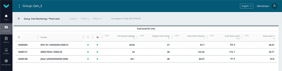
a) real-time display of information on the *Fuel Level dashboard
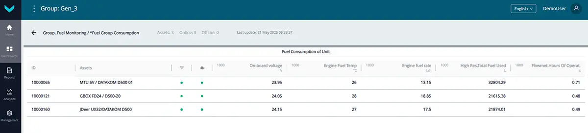
b) real-time display of information on the *Fuel Group Consumption dashboard
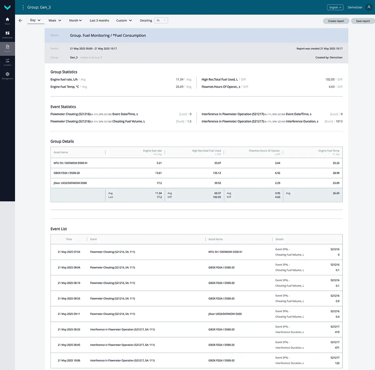
c) analytical report *Fuel Consumption for the “one-day” period
Figure 13 — Examples of default data display for the Group. Fuel Monitoring task
2.4 Group. Location Tracking #
Task class: 25.
Purpose:
Group. Location Tracking — this task is used for real-time map-based tracking of the exact location and movement routes of a group of mobile diesel generators (assets), as well as for detailed analysis of their movements over a selected time period.
Equipment used:
- CANUp 27 Genset telematics gateways – up to 20 pcs.
Total keys: 25 pcs.
Preconfigured keys: 9 pcs. (see table 14).
Free keys: 16 pcs.
Table 14 — Preconfigured keys for the Group. Location Tracking task
| Source network address* | SPN and specifier (if applicable) |
Unit of measurement | Description |
| 1000 | 517 Navi.-Based Vehicle Spd | km/h | Current speed of each genset in the group, determined based on GNSS data. |
| 1000 | 580 Altitude | m | Current altitude above sea level of each genset in the group, determined based on GNSS data. |
| 1000 | 584 Latitude | degrees | Latitude coordinate of the current location of each genset in the group, determined based on GNSS data. |
| 1000 | 585 Longitude | degrees | Longitude coordinate of the current location of each genset in the group, determined based on GNSS data. |
| 1000 | 521090 HDOP | No | Current Horizontal Dilution of Precision (HDOP) value for each genset in the group. HDOP is a coefficient that indicates the accuracy of the object’s current position in the horizontal plane. The HDOP value may range from 1 (maximum accuracy) to 50 (minimum accuracy). |
| 1000 | 521126 Distance by GNSS | m | Total distance traveled by each genset in the group since it was equipped with a telematics gateway. This counter can be reset by the user. |
| 1000 | 521128 Satellites Quantity | pcs. | Current number of navigation satellites visible to the telematics gateway of each genset in the group. |
| 1000 | 521155 UTC Time by GNSS | s | Current time of the telematics gateway for each genset in the group. Time is in UTC format, determined based on GNSS data. |
| 1000 | 521384 Acceleration Module | m/s² | Current value of the total linear acceleration for each genset in the group across the three coordinate axes (X, Y, Z). It is calculated as the square root of the sum of the squares of the current linear accelerations along each axis. If the value exceeds the motion filtering threshold set in the telematics gateway settings (SPN 521341), the movement status is automatically detected. |
| * The source address (SA) of each key used in group tasks is always set to 1000, regardless of the source addresses of similar keys for individual assets within the group. |
|||
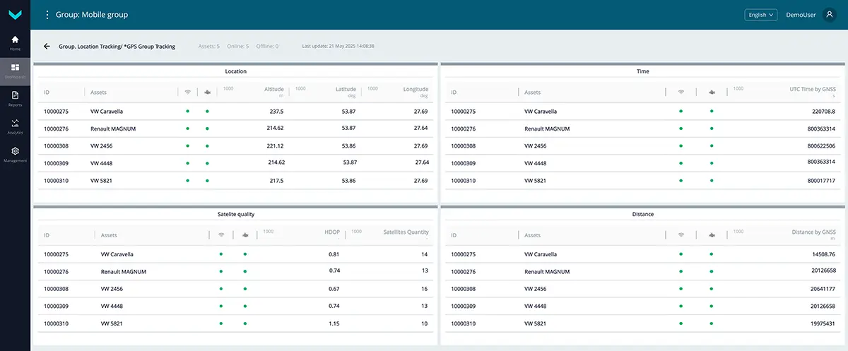
a) real-time display of information on the *GPS Group Tracking dashboard
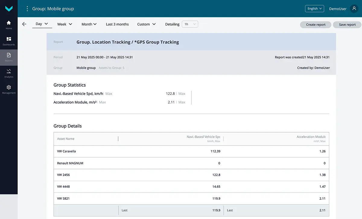
b) analytical report *GPS Group Tracking for the “one-day” period
Figure 14 — Examples of default data display for the Group. Location Tracking
2.5 Group. System Self-Diagnostics #
Task class: 25.
Purpose:
Group. System Self-Diagnostics — this task is used for real-time monitoring or analysis over a selected period to assess the performance quality of the onboard equipment for a group of diesel generators.
Equipment used:
- DUT-E / DUT-E 2Bio / DUT-E S7 / DUT-E 2Bio S7
fuel level sensors – up to 160 pcs.; - DFM / DFM D / DFM S7 / DFM D S7 / DFM Marine / DFM Marine S7
fuel flow meters – up to 160 pcs.; - MasterCAN Display 35 CAN j1939/S6 displays – up to 40 pcs.;
- MasterCAN DAC15 digital-to-analog converter – up to 20 pcs.;
- CANUp 27 Genset telematics gateways – up to 20 pcs.
Total keys: 25 pcs.
Preconfigured keys: 24 pcs. (see table 15).
Free keys: 1 pcs.
Table 15 — Preconfigured keys for the Group. System Self-Diagnostics task
| Source network address* | SPN and specifier (if applicable) |
Unit of measurement | Description |
| 1000 | 158 On-board voltage | V | Onboard voltage (from the ignition switch) of each genset in the group, based on data from the corresponding telematics gateway. |
| 1000 | 521049 Ignition Key State 16. Working time from power supply : 2. Ignition switch terminal 15 |
No | Current ignition key status (On/Off) for each genset in the group. The “On” state corresponds to the presence of voltage at terminal 15 of the ignition switch. |
| 1000 | 521050 Battery Level State | No | Current charge status of the built-in battery of the telematics gateway for each genset in the group (fully charged / charging / charge status error / battery unavailable). |
| 1000 | 521056 Vehicle Power Supp.Stat. | No | Current onboard power mode of each genset in the group, determined according to user-defined voltage thresholds (Off / Low level / Battery / Starter / Generator / High level). |
| 1000 | 521072 Reports Counter | pcs. | Current number of reports registered by each genset in the group. |
| 1000 | 521072 Reports Counter 21. Priority : 0. Emergency |
pcs. | Current number of emergency event reports (e.g., “Alarm”) registered by each genset in the group. |
| 1000 | 521072 Reports Counter 21. Priority : 1. Important |
pcs. | Current number of important event reports (e.g., “Fuel discharging”, “Fuelling”) registered by each genset in the group. |
| 1000 | 521116 Unit Hours Of Operation1 | s | Total runtime counter value of the telematics gateway for each genset in the group since its manufacture. This counter cannot be reset by the user. |
| 1000 | 521116 Unit Hours Of Operation1 16. Working time from power supply : 1. Battery |
s | Total runtime counter value of the telematics gateway for each genset in the group when powered by the internal battery (in the absence of external power) since its manufacture. This counter cannot be reset by the user. |
| 1000 | 521118 Unit Reset Counter | pcs. | Processor restart counter of the telematics gateway for each genset in the group, triggered by power-up or conductive interference in the onboard network. The count is maintained from the time the telematics gateway is manufactured and cannot be reset by the user. |
| 1000 | 521129 Unit Power Status | No | Current power status of the telematics gateway for each genset in the group (powered by internal source / powered by onboard network / power off / power status detection not supported or unavailable). |
| 1000 | 521131 Modem Registration Stat. | No | Current registration status of the GPRS modem of the telematics gateway for each genset in the group in the mobile operator’s network (No network / Home network / Roaming). |
| 1000 | 521134 GNSS Receiver Status | No | Current operational status of the built-in GNSS receiver of the telematics gateway for each genset in the group (On / Error). |
| 1000 | 521135 GNSS Antenna Status | No | Current connection status of the built-in GNSS antenna of the telematics gateway for each genset in the group. For a built-in GNSS antenna, the status is always “Connected.” |
| 1000 | 521144 AVL Connection Counter | pcs. | Current number of GPRS modem connections from the telematics gateway of each genset in the group to the AVL server. The user can reset all counter values simultaneously, if necessary. |
| 1000 | 521145 AVL Connect.Fail.Counter | pcs. | Current number of connection errors between the GPRS modem of the telematics gateway and the AVL server for each genset in the group. The user can reset all counter values simultaneously, if necessary. |
| 1000 | 521146 AVL Disconnect. Counter | pcs. | Current number of GPRS modem disconnections from the AVL server for each genset in the group. The user can reset all counter values simultaneously, if necessary. |
| 1000 | 521173 Hours Of Operation On Power Supply | pcs. | Total runtime counter from the onboard power supply since the installation of the telematics gateway for each genset in the group. |
| 1000 | 521176 AVL Authent.Count. | pcs. | Current number of successful authentications of the telematics gateway for each genset in the group on the AVL server. The user can reset all counter values simultaneously, if necessary. |
| 1000 | 521177 AVL Authent.Fail.Count. | pcs. | Current number of authentication errors of the telematics gateway for each genset in the group on the AVL server. The user can reset all counter values simultaneously, if necessary. |
| 1000 | 521178 RSSI | dBm | Current received signal strength indicator (RSSI) level on the logarithmic scale for the GPRS modem receiver of each genset’s telematics gateway in the group. Output range: from -52 to -115 dBm. |
| 1000 | 521190 Engn Hours Of Operation | s | Total engine runtime counter across all load ranges for each genset in the group. This counter can be reset by the user. |
| 1000 | 521334 GSM Network Mode | No | Cellular communication standard currently used by the built-in GSM modem of the telematics gateway for each genset in the group (2G / 3G / 4G). |
| 1000 | 521488 Unit DTCs Mask | No | Fault mask of the telematics gateway for each genset in the group. |
| * The source address (SA) of each key used in group tasks is always set to 1000, regardless of the source addresses of similar keys for individual assets within the group. |
|||
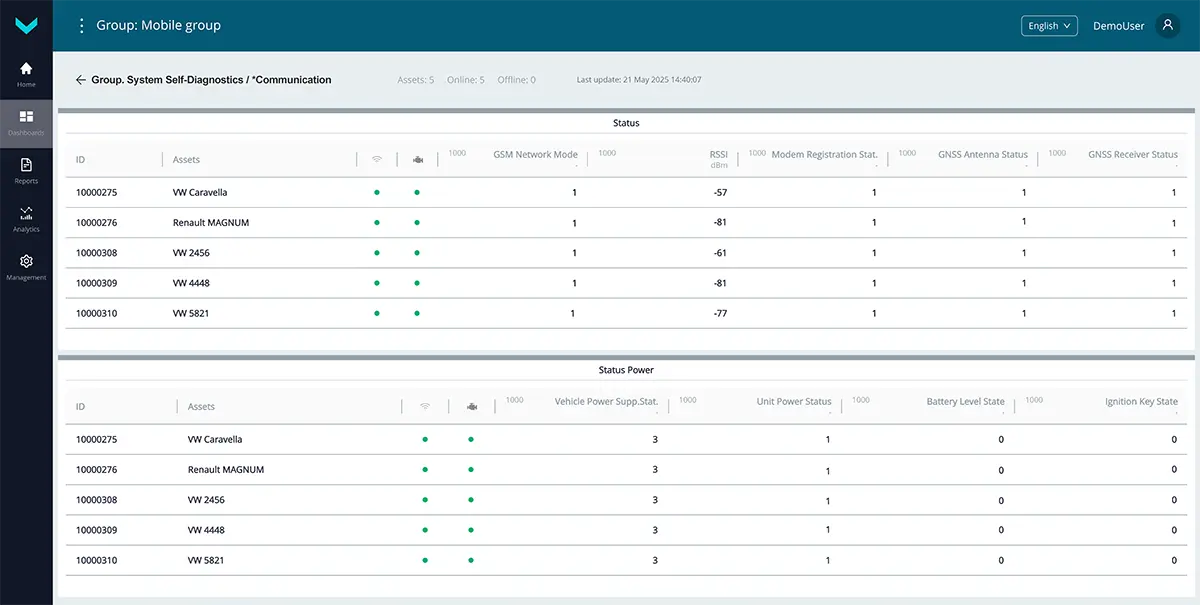
Figure 15 — Example of real-time display on the *Communication dashboard showing default data for the Group. System Self-Diagnostics task